Antenna Azimuth Position Control System
Antenna Azimuth Position Control System. Team: By Tyrone Tracy Sukhbir Hundal Bee Thao ME 270 12/13/07. Overview. Objective System Concept Textbook Schematic Bondgraph Models Results Conclusion Demonstration Model. Objective.

Antenna Azimuth Position Control System
E N D
Presentation Transcript
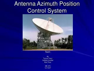
Antenna Azimuth Position Control System Team: By Tyrone Tracy Sukhbir Hundal Bee Thao ME 270 12/13/07
Overview • Objective • System Concept • Textbook Schematic • Bondgraph Models • Results • Conclusion • Demonstration Model
Objective • Replicate results from Norman S. Nise’s Antenna Azimuth Position Control System Using Camp-G/Matlab/Simulink • Transfer Functions • System Response Graphs
*Control System Engineering by Norman S. Nise System Concept
Block Diagram Parameters
Bond Graph Models • Three individual systems • Differential preamplifier • Power amplifier • DC motor • Complete System
Differential Preamplifier Control System Engineering Model CampG Model Modified Model
Differential Operational Amplifier • Textbook Results Transfer Function Step Response
Differential Preamplifier • Matlab • Our Results • Simulink
Differential Preamplifier Equation dQ5=SE1/R3-Q5/C5/R3
Power Amplifier Control System Engineering Model CampG Model Modified Model
Power Amplifier • Textbook Results Transfer Function Step Response
Power Amplifier • Matlab • Our Results • Simulink
Power Amplifier Equation dQ6=-SF1+SE12/R11-Q6/C6/R11-Q6/C6/R7
DC Motor Control System Engineering Model CampG Model Modified Model
DC Motor • Textbook Results Transfer Function Step Response
DC Motor • Matlab • Our Results • Simulink
DC Motor Equations dP8=SE1/R2/G3x4/T6x7-P8/I8/T6x7/G3x4/R2/G3x4/T6x7-P8/I8/T6x7*R5/T6x7-P8/I8*R9-P8/I8*T10x11*R12*T10x11
Complete System • Textbook Results Transfer Function Step Response
Complete System • Matlab • Our Results • Simulink
Differential Equations 1. dQ24=SF1-Q24/C24/R232. dQ28=SE25/R27-Q28/C28/R273.dP8=P8/I8/T6x7/G3x4/R2/G3x4/T6x7+SE18/R2/G3x4/T6x7-P8/I8/T6x7*R5/T6x7P8/I8*R9*P8/I8*T10x11*R12*T10x11
Conclusion • Comparison • Results Very Close • Graphs were similar • Transfer Functions almost exact • Error • About 5 percent error • Conclusion • We are able to use CampG/Matlab/Simulink to reproduce Nise’s book results!!!
Demonstration Model • Our Antenna Azimuth Position Control System • The video is also located in the folder!