Camshaft Construction
410 likes | 806 Vues
Camshaft Construction. Camshaft Construction. Materials Cast iron Chilled iron Forged steel Steel billet. Camshaft Features. Lobes Journals Distributor drive gear (if used) Flange and locating dowel for timing gear/sprocket/pulley. Camshaft Wear Limits.

Camshaft Construction
E N D
Presentation Transcript
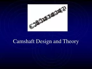
Camshaft Construction • Materials Cast iron Chilled iron Forged steel Steel billet
Camshaft Features • Lobes • Journals • Distributor drive gear (if used) • Flange and locating dowel for timing gear/sprocket/pulley
Camshaft Wear Limits • Cam wear specifications are often not listed in service information • If information is not available these general specifications should be used • Journal wear limit - .0015” max • Warpage - .002” max • Lobe wear - .002” max • Lobe surface hardness 48 – 58 Rc
Camshaft Lubrication • Cam journals are pressure fed by oil passages in block • Due to the fact that cam journals don’t have fillets there is more oil pressure lost here than any place in the engine • Holes in the rear cam journal prevent oil pressure buildup which could cause a cam walking forward or the cam plug blowing out • Cam lobes are splash oiled • Lifter rotation is critical to proper lobe/lifter wear • Lifter bore is offset to the cam lobes
Cam Lobe Design • Lobes on a flat tappet cam are tapered by about .002” (larger towards the rear of the engine) • This promotes lifter rotation and forces the cam rearward in the block • Lobes on a roller cam are flat
Cam/Lifter Designs • Flat tappet hydraulic • Flat tappet mechanical • Roller hydraulic • Roller mechanical • Mushroom
Flat Tappet Cams • Lifters are slightly convex • A flat or concave lifter indicates improper wear • Lobes are tapered • May be hydraulic or mechanical design • Lifter rotation is critical • Accomplished by lobe taper, a convex lifter and/or an offset lifter bore • Flat tappet cams are limited by how fast they can open and close the valve. • Too fast of an opening will cause the lifter to “dig in” to the lobe
Roller Cams • Lobes are flat – requires thrust control • Lifters utilize some type of anti-rotation device • Cams are generally made from steel to withstand the higher pressures • Distributor gear on a steel cam may not be compatible with a stock distributor gear (use a bronze gear on distributor) • Higher opening speeds are allowed by the aggressive ramp profile and roller tipped lifter • This allows more lift and “area under the curve” than a flat tappet cam of the same duration
Mechanical “Solid” Cams • May be flat tappet or roller design • Requires “valve lash” or clearance between the rocker arm and the valve tip when cold • When engine heats up, valvetrain components expand. If there is insufficient valve lash this will cause the valve to hang slightly open at all times • As valvetrain wears, lash must be adjusted occasionally • Solid lifters are generally slightly lighter than a hydraulic lifter which helps curb valve float • Solid lifters don’t “pump up” or collapse at higher rpm's like hydraulic lifters can
Hydraulic Cams • Hydraulic lifters use engine oil pressure and an internal valve system to maintain zero lash • Hydraulic lifters eliminate need for periodic lash adjustments • Hydraulic lifters were generally limited to 6000 RPM, but new technology has pushed that to higher limits • Variable duration or “fast bleed down” hydraulic lifters allow a long duration cam to work better at low RPM
Mushroom Lifters • Usually a solid lifter design • The larger foot of the lifter allows a faster opening lobe and reduces wear
Camshaft Drives • Gear to gear • Sprockets and chain • Sprockets and belt
Gear to Gear • Usually helical cut to reduce noise • Backlash or clearance between gears is very important to their life
Chain and Sprocket • Used in both “in-block” and OHC engines • Two types of chains used • Link • Roller chain • May have provisions for adjusting cam timing • OHC engines generally will use a tensioner (may be hydraulic)
Belt and Sprocket • Belt is fiberglass reinforced • Do not bend the belt sharply, you will damage the fiberglass fibers
Valvetrain Setups • Valve in block • OHV • OHC • DOHC
Other Valvetrain Components • Pushrods • Rocker arms • Valve springs • Valve retainers • Valve keepers (locks)
Pushrods • Construction • Cast type • Tubular type • Different length pushrods are available for adjusting valvetrain geometry • Service • Check for bent pushrods by rolling on a piece of glass • Check ends for wear, galling, or hole enlargement • If there are a lot of deposits in the engine, pushrods should be replaced when rebuilding an engine if they cannot be properly cleaned
Rocker Arms • Materials • Cast steel • Stamped steel • Aluminum • Billet steel • Designs • Stud-mount • Shaft mount • Adjustable • Non-adjustable • Friction pivot • Roller
OHC • Valve actuation may uses various designs • Bucket lifters • Rocker followers • Finger followers
Bucket Lifters • Shaped like an inverted bucket • Either uses a replaceable shim or a hydraulic design to control lash
Rocker Followers • Pivots on shaft or ball studs • Works like a typical pushrod system minus the pushrods and lifters
Finger Followers • Looks like a bridge between pivot and valve tip • Cam lobe contacts the middle • Adjustment at pivot point may be mechanical or hydraulic Follower Pivot
Valve Springs • Valve springs may be single double or triple • Valve springs may include a harmonic damper (flat wire) • Valve springs must be matched to the cam and the intended RPM use • To little tension may cause valve float or bounce • To much tension may cause excessive lobe wear
Installed Height • Assuring the correct installed height will assure correct spring pressures.
Valve Retainers • Valve retainers transfer the load from the valve keepers to the valve springs • Special retainers must be used for double or triple springs • Special retainers must be used if 10 degree valve locks are used • Retainers are also available for adding additional valve spring installed height
Valve Locks (Keepers) • Valve locks transfer the load from the valve to the retainer • Valve locks are available in either 7 or 10 degree styles • Valve keepers are also available for adding additional valve spring installed height
Valve Seals • Styles • O-ring (cheap, simple) • Prevents the oil from running between the valve stem and retainer and then down the valve stem • Umbrella (more effective) • Keeps oil from running down the valve stem and into the guide • PC seal (most effective) • Seal on the valve stem and on the top of the guide