Digital Circuit Testing: Fault Detection and Localization
210 likes | 236 Vues
Learn about testing digital circuits, including the need for testing at the manufacturer and user ends, different fault scenarios, fault models, and test generation methods.

Digital Circuit Testing: Fault Detection and Localization
E N D
Presentation Transcript
ECE465: Lecture #12Digital Circuit Testing Shantanu Dutt UIC Acknowledgement: Initial slides prepared by Huan Ren from Prof. Dutt’s Lecture Notes (significant modifications/additions made subsequently by Prof. Dutt).
Vdd stuck-at-on Testing of Combinational Circuit • Complex submicron chips / multi-chip PCBs possibility of errors in the manufacturing process physical faults in the digital circuits • Need to test at manufacturer before shipping out • Need to test periodically at user end as faults can also develop due to various circuit stresses (high temp, moisture, impact, etc.) • Testing Scenarios • Fault-detecting test set (FDTS): inputs (test vectors) detecting presence/absence of faults (under certain assumptions, e.g., single fault). • Fault-locating test set (FLTS): inputs locating the fault(s). • CUT: Circuit under test . • Signature: Compaction of all O/Ps • Fault Models • Types: permanent, intermittent, transient responses • Many possible physical faults: E.g., broken or shorted wires, defective transistors, noise, improper power voltage Wire break (s-a-0) Wire short to GND (s-a-0) Defective transistor (always on)
Bridging fault (2 signal wires shorted) Vdd s-a-on s-a-1 Fault Models (Contd.) • A good fault model that can account for the logical behaviors of most faults is the “stuck at” fault model: s-a-0, s-a-1 for each interconnect/wire in the circuit • The s-a-0/1 fault model accounts for most physical fault types but not all. E.g., it does not account for ‘bridging’ faults) since we cannot say if either wire is s-a-0 or s-a-1—this situation will change dynamically based on the values (1 or 0) being driven on the wires and which driver is stronger Wire break (s-a-0) Wire short to GND (s-a-0) Defective transistor (always on)
x1 x2 x3 f 4 5 4 1 3 2 1 2 3 4 5 1 5 3 2 s-a-1 s-a-0 Function Notations in Fault Circuits f(x3)=x1x2+x3 For f(xn)=f(x1, x2,…,xn), let p be a wire in the circuit and d in {0,1}. Then fp/d(x1,…,xn) is the function for the faulty circuit with wire p s-a-d. x3 x3 E.g., f3/0( )=x1x2, and f2/1( )=x1+x3 x1 x1 x2 f3/0 x2 x3 x3 f2/1
Expected responses Compare Fault Testing • Circuits with r wires have 2r different single faults and 3r-1 possible single/multiple faults. • Exhaustive testing is impractical for large circuits since it take O(2n) time for n-inputs. Test vector CUT O/Ps … … • Need to determine a minimum set of inputs that can test for (detect/catch) any single fault. Single fault detection is a good goal as: • Probability of multiple faults is much lower than single faults • Mutiple faults take much more time to detect
Test Generation • Function: f(x1,…,xn) (≡f(Xn)) represents the fault-free circuit. • A test Ti for fault p/d is an input vector Xnj to the circuit for which: fp/d(Xnj) = f(Xnj) where j is the decimal value of the n bit binary input. • E.g., X31 =001 is a test for 3/0 for the earlier example: as f(X31)=1 and f3/0(x31)=0 • An alternative way of looking at this provides the basis for the EX-OR method of test generation: • The above condition implies Xnjis a test for p/d iff: f(Xnj) + fp/d(Xnj)=1 • The minterms (MTs) of Fp/d= f + fp/d are tests for p/d. , f3/0(x3)=x1x2] [f(x3)=x1x2+x3
EX-OR Method [f(x3)=x1x2+x3] • MTs of Fp/d=f + fp/d are tests for p/d. Can be determined algebraically • E.g., In the previous example F1/0=(x1x2+x3) + x3=x1x2x’3. Hence, test=110 (only MT for F1/0 ) for 1/0 F3/0=(x1x2+x3) + x1x2 = x’1x3+x’2x3. Hence, test=001, 011,101 (MTs of F3/0) • These tests (MTs of Fp/d) can also be determined in a tabular manner as shown below, but this is more cumbersome
Fault Table • Displays a set of faults (generally single faults) and a set of test inputs that test them (i.e., detect them)—can be drived, for ex., from the XOR table • A “1” at the intersection of i/p vector Xnj and fault p/d Xnj is a test for p/d • A “0” at the intersection of i/p vector Xnj and fault p/d Xnj is not a test for p/d
*(ETV) 1 *(p-ETV) 6 *(ETV) 2 *(ETV) 3 1 3 4 1 3 3 2 3 1 1 Determining a Minimal Test Set • A test set for a fault set S is a set of i/p vectors (also called test vectors [TVs]) which contains at least one test for each fault in S • From the fault table, we need to determine a minimal test set that covers all faults in the table (the set of faults in the table is the set S) • Determining a minimal test set lower testing cost in terms of • Test time (this allows, for ex, product to get to market faster after manufacturing testing) • Power consumption during testing • Determining a minimal test set is a minimal covering problem, just like in the PIT part of QM where we need to cover all MTs w/ a minimal set of PIs (this is especially true in PLA design, where each PI has a cost of 1). • Here, TVs PIs and faults MTs • So a QM-type method can be used for covering all faults using a minimal set of TVs • TV cost = 1, and since there is no multi-function type issue as in QM for logic min., costs are not mentioned • After all the essential TVs (ETVs) and their faults are deleted on fault 3/0 remains • In the reduced fault table (RFT), all TVs covering 3/0 cover each other & all but one can be deleted (dels not shown here for simplicity) • We choose to not delete TV 011, & it is thus chosen to cover 3/0 • Final minimal test set = {010, 011, 100, 110} 4 5
Wire p Wire p FT d’ d’ p2 p2 z z z z z’ 1 1 p1 p1 s-a-d (p/d) s-a-d (p/d) 0 0 z z 0 0 p3 p3 BT BT Circuit I/Ps BT BT I/P cone of p3 Path Sensitizing method • XOR method can be very cumbersome for leven medium-size circuits. • An alternative more time-efficient method: Path Sensitizing method • Select a path from fault-site p to ckt. o/p(s). For fault p/d, z is the “fault value” (z = d if there is a fault p/d) • Forward Trace (FT): • Choose intermediate logic values at gate i/ps along the path, so that logic values of lines/wires in the path are functions of z (i.e., z or z’). • Also, choose the complement value d’ to the fault value to be “injected” at the fault line ( for no fault @ p, z = d’) • The path is then said to be “sensitized” from the fault site to the o/p. • Backward Trace (BT): • Trace backwards and establish circuit inputs, if possible, required for obtaining the logic values at different points in the sensitized paths determined during FT. • If there is a “conflicting” values needed at any i/p or intermediate points/wires during BT thre is no test for p/d • Don’t cares (X’s) at i/ps after BT w/ no conflict anywhere else multiple tests for p/d (<= 2k tests if k i/ps have X’s after BT) • This method may not yield all possible tests for a fault p/d (unlike the XOR method) • This can compromise minimal test set determination • If the reqd values shown above for wires p, p1, p2 and p3, can be “injected” into them via some TV at the ckt i/ps (such TV(s) are determined during BT) we have a test for p/d, since: • If there is a fault p/d, z = d, and o/p = z’ = d’ • If there is no fault @ p, z = d’ (d’ is injected at p) o/p = z’ = d • Thus o/p for p/d != o/p for no fault @ p
z z z z Path Sensitizing method (contd) 1/0 1/1 1/0 1/1 • Examples of sensitized i/ps for different gates • Can also determine these for other gates/components (e.g., XOR, XNOR, AOI, MUXes) Two input z x1=1 z x1=0 x1=1 x1=0 z z z z z z x2=0 x2=0 x2=1 x2=1 OR gate w/ s-a-0 OR gate w/ s-a-1 AND gate w/ s-a-0 AND gate w/ s-a-1 Four input 2/0 2/1 2/0 2/1 x1=0 x1=0 x1=0 x1=0 x2=1 x2=0 x2=1 x2=0 z z z z x3=0 x3=0 x3=0 x3=0 z z x4=0 x4=0 x4=0 x4=0 2/0 2/1 2/1 2/0 x1=1 x1=1 x1=1 x1=1 x2=1 x2=0 z x2=0 x2=1 x3=1 z x3=1 z z z x3=1 x3=1 x4=1 z x4=1 x4=1 x4=1
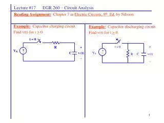
Forward trace BT 1 x1=1 x2=1 1 z x3=0 z 0 1 1 2 5 4 3 4 2 3 5 Path Sensitizing method (contd) Backward trace 1/0 z x1=X/0 f x2=0/X f 0 z z x3=0 z 0 3/1 Forward trace Confirm w/ XOR method: F1/0=(x1x2+x3) + x3=x1x2x3’ test for 1/0 = {110} Confirm: F3/1=(x1x2+x3) + 1 = (x1’+x2’)x3’ = x1’ x3’ + x2’x3’ tests for 3/1 = {000, 010, 100}
x1=X/0 x2=0/X 4 1 2 3 5 z z’ p1/d p6/d p8/d p7/d’ Test Xnj z z’ z d’ z’ p4/d z’ p2/d’ 2 sensitized paths for p1/d p5/d’ z p3/d’ Path Sensitizing method (contd) • Facts in fanout-free circuits (circuits in which each gate o/p feeds only 1 gate i/p or is a ckt o/p) and circuits w/ fanout (at least 1 gate o/p feeds > 1 gate i/ps): • For a given sensitized path, each wire along the path for p/d is also tested for a s-a-0 or s-a-1 fault as determined as follows: • For each wire w on the sensitized path, if logic value on w is z, then w is tested for w/d, otherwise (logic value on w is z’) it is tested for w/d’ • In Fig. 1 below, a test for 3/1 is also a test for 5/1 (the sensitized path is 3 5) • There is only 1 path from an i/p to an o/p each wire is on at least one (unique) path from an i/p to an o/p • Thus fan-out free ckts can be tested for all possible single s-a-0 and s-a-1 faults by testing each primary input for s-a-0 and s-a-1 faults • For fanout ckts, if the faulty point has a fanout, then its test will test all sensitized paths for that test; but all fanout paths from a fault may not be sensitized; so a faulty point’s test is not necessarily a test for all fanout paths • Thus should try to do multipath sensitization (either simultaneously or sequentially) if possible (it is not always!) in fanout ckts. For sensitization of simultaneous paths, when the paths are reconvergent, then only under special cases (given later) will tests for the primary fault be tests for wires on these paths • If after tests for primary i/ps and their sensitized paths are determined for all possible faults, if some wires remain untested (because a path to them from primary i/ps cannot be sensitized), start the process from such wire(s) w/ the lowest level and find tests for them and all their sensitized paths Backward trace Forward trace f 0 z z x3=0 0 Fig. 2: Xnjis a test for p1/d, p2/d’, p3/d’, p4/d & p5/d’ on path1 and p6/d, p7/d’ & p8/d on path 2 if sensitized non-simultaneously 3/1 Fig. 1: Test set for 3/1 & 5/1 = {000, 100, 010}
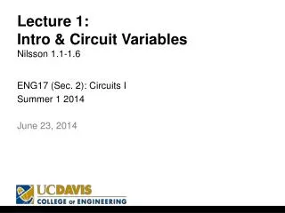
2/0 2/0 1 0 x1=1 x1=0 0 z x2=1 x2=1 z z z 1 z 1 z 0 x3=0 x3=1 5 6 5 4 5 4 6 4 6 Testing Circuits with Fanout • Path sensitization: a) Multiple or single paths can be sensitized. • Single path sensitized by TV 110; also a test for 4/0, 6/0. • Further, the path is sensitized also for fault 2/1, except for a 0 needed now to be injected on wire 2. Thus if wire 2 is a primary i/p and does not provide any of the “other” i/ps to any gate on the senstitized path, then just by changing the corresponding i/p from 1 to 0, we get a test vector 100 for 2/1 (and 4/1, 6/1). • Another single path sensitized by TV 011; also a test for 5/0 & 6/0. • Further, as in the top path sensitization, the vector 001 is a TV for 2/1 (and 5/1, 6/1) • Double path sensitized by TV 111 • However, this TV is not a test for 4/0, 5/0. E.g., consider fault 4/0. Since if 2 is non-faulty (nf)—we are testing for only single faults—wire 2 takes on value 1, which causes a 1 on wire 5, thus not sensitizing the path from wire 4 to the o/p 6. • It is, however, a test for 6/0, since wire 6 occurs after the two paths reconverge (check out that 111 injects a 1 into 6) • The corresp. double path sens. based test for 2/1 is 101 (as discussed above) • TV 101 is also a test for 4/1, 5/1 and 6/1. E.g., consider 4/1. TV 101 injects a 0 into 4 (needed as the complement of the s-a-1 on 4), and on 5, needed for sensitizing the path from 4 to o/p 6 Reconvergence point/gate of the 2 fan-out paths 2/0 1 x1=1 z x2=1 z z 1 z x3=1 1
z z’ p8/d p1/d p6/d z p7/d’ o/p1 z’ z d’ z’ p4/d z’ p2/d’ o/p2 2 sensitized paths for p1/d p5/d’ z p3/d’ Test Xnj Testing Circuits with Fanout---Multipath sensitization • From the previous example, we can obtain (and prove) the following rules for determining when a test for an initial fault location p/d determined using multipath sensitization, is also a test for subsequent wires on these paths: • (a) If the multiple sensitized paths are not reconvergent, as shown above, then the wires pj on each path is also tested by the determined TV(s) for p1/d, based on whether the logic variable on wire pj is z—the logic variable on p1—(tested for pj/d) or z’ (tested for pj/d’)
z z’ p1/0 p6 p8 p7 z z z’ z z’ 1 z p4 z’ p2 p9/0 p10/1 2 sensitized paths for p1/0 p5 z p3 No tests for these wires z z’ p8/1 Reconvergence point/gate Reconvergence point/gate p1/1 p6/1 p7/0 z or or z z’ z z’ 0 z p4/1 z’ p2/0 p9/1 p10/0 2 sensitized paths for p1/1 z p5/1 p3/0 Test Xnj Test Xnj Testing Circuits with Fanout---Multipath sensitization (contd) • (b) If: (i) the test is for p1/0, (ii) the multiple sensitized paths are reconvergent at an OR or NOR gate, and (iii) the i/ps to this gate are all z, as shown above, then the tests determined this way for p1/0 are not tests for any pj/d (d= 0 or 1) for wires pj on each path from p1 to the reconverging gate. However, from the reconvergent point onwards, wires pk are also tested by the determined TV(s) for p1/0, based on whether the logic variable on wire pk is z—the logic variable on p1—(tested for pk/0) or z’ (tested for pk/1) • (c) If: (ii) the test is for p1/1, (ii) the multiple sensitized paths are reconvergent at an OR or NOR gate, and (iii) the i/ps to this gate are all z, as shown above, then the tests determined this way for p1/1 are also tests on subsequent wires pj on these paths for pj/d (d= 1, 0 for logic z, z’ resp. on pj) as shown above • (d) The above two situations are completely reversed when condition (iii) in (b)-(c) changes to: (iii) the i/ps to the reconvergent gate are all z’ (the first 2 conditions in (b) remaining unchanged) as follows: • Alternate of (b):All the p1/0 test(s) determined here are also test(s) for the intermediate wires s-a-0/1 (based on z/z’ var, resp. on them) on the sensitized paths. This is b/c for an intermediate wire pj, z’ on the other path(s) (the one(s) not containing pj) = 0 path through pj via the reconv. OR/NOR gate is sensitized • Alternate of (c):None of the the p1/1 test(s) determined here are tests on the intermediate wires on these paths before the reconvergent point (since z’ on the “other” path(s) = 1 thus not sensitizing the path through pj). They, are, however, tests for wires after the reconvergent gate.
z z’ p1/1 p6 p8 p7 z z z’ z z’ 0 z z’ p4 p2 p9/1 p10/0 2 sensitized paths for p1/1 p5 z p3 No tests for these wires z z’ Reconvergence point/gate Reconvergence point/gate p1/0 p6/0 p8/0 p7/1 or or z z’ z z z’ 1 p4/0 z’ z p2/1 p9/0 p10/01 2 sensitized paths for p1/0 p5/0 z p3/1 Test Xnj Test Xnj Testing Circuits with Fanout---Multipath sensitization (contd) • (e) If: (i) the test is for p1/1, (ii) the multiple sensitized paths are reconvergent at an AND or NAND gate, and (iii) the i/ps to this gate are all z, as shown above, then the tests determined this way for p1/1 are not tests for any pj/d (d= 0 or 1) for wires pj on each path from p1 to the reconverging gate. However, from the reconvergent point onwards, wires pk are also tested by the determined TV(s) for p1/1, based on whether the logic variable on wire pk is z—the logic variable on p1—(tested for pk/1) or z’ (tested for pk/0) • (f) If: (i) the test is for p1/0, (ii) the multiple sensitized paths are reconvergent at an AND or NAND gate, and (iii) the i/ps to this gate are all z, as shown above, then the tests determined this way for p1/0 are also tests on subsequent wires pj on these paths for pj/d (d= 0, 1 for logic value z, z’, resp., on pj) as shown above • (g) The above two situations are completely reversed when condition (iii) in (e)-(f) changes to: (iii) the i/ps to the reconvergent gate are all z’ (the first 2 conditions remaining unchanged) as follows: • Alternate of (e):All of the p1/1 test(s) determined here are test(s) for the intermediate wires s-a-0/1 (based on z/z’ var, resp. on them) on the sensitized paths. This is b/c for an intermediate wire pj, z’ on the other path(s) (the one(s) not containing pj) = 1 path through pj via the recconv. AND/NAND gate is sensitized • Alternate of (f):None of the the p1/0 test(s) determined here are tests on the intermediate wires on these paths before the reconvergent point (since z’ on the “other” path(s) = 0, thus not sensitzing the path through pj). They, are, however, tests for wires after the reconvergent gate. • (h) There cannot be simultaneously sensitized paths reconvergent on 2-i/p XOR/XNOR gates (the paths cannot be sensitized beyond such gates), & thus such gates are not considered here.
z z z z Testing Circuits with Fanout (contd) • Path sensitization (contd) • b) In some cases, only single path sensitization will work and multiple will not (fault freeO/P->O/P with fault at ckt O/P will be either 1->1 or 0->0, thus not detecting the fault.). 1 2/0 (1->0) p/0 1->1 x1=1 z 1->0 z z 1 1 z x2=1 z z General case. 0 x3=0 Single path sensitized by TV 110 2/0 2/0 Not a function of z 1 x1=0 x1=1 0 0->1 z z x2=1 x2=1 z 1 z (1->1) x3=1 x3=1 1 1 Single path sensitized by TV 011 Double path produced by 111 is not a test
0 0 1 1 1 1 Testing Circuits with Fanout p/1 1 Not possible to get a 0, but may be possible get a z at an intermediate gate on the path being sensitized in the FT 1/z z 1 z 0->1 • Path sensitization (contd) • c) In other cases, single path sensitization will not work, and only multiple path will. x1=1 z 1/z (either possible) x2=0 &1 1 0 General case Need to get a z instead of 1 for sensitization Forward trace OK, but backward trace fails. Conflict! p/1 1 Double path produces a test (11) z 0->1 x1=1 z x2=1 z 1
Summary of Path Sensitization • Overall Technique for Fanout-Free Circuits: • Sensitize the unique path P(p,q) from a primary inp. p to an op. q, for p/d, and get corresponding tests for all wires along this path. • Repeat process for p/d’ sensitization (sometimes very easy to derive from p/d sensitization as in prev. examples, but sometimes not, in which case have to do from scratch), and obtain the tests for the complement faults of wires on P(p,q) • Overall Technique for Circuits with Fanout: • In turn, try single path sensitization from inp. p to op. q on each path from p q for p/d until sensitization obtained. When this is attained, the tests for the successful path will be tests for corresponding faults on all wires on this path as explained earlier. (An option is not to stop at the 1st successful path, but to continue until all possible single paths from p q are sens. as this gives us more tests for p/d to choose from in the fault table and also provides tests for additional wires on these paths.) • Repeat above process for p/d’ • If single path sensitization is not possible for p/d or p/d’, then try all possible multiple paths in turn from 2 paths onwards as explained earlier. If sensitization is obtained, then as explained earlier, the tests obtained for p/d or p/d’ (as the case may be), may or may not be a test for wires of these simultaneously sensitized paths • If after tests obtained for all primary inputs via the above process, some internal wires still have no tests, then repeat the above steps for each such internal wire p, in order of increasing “levels” of such wires (i.e., starting from those at the smallest level, since tests for smaller level wires can yield test for higher level ones if on the same sensitized paths) • Pros and Cons: • Adv over XOR method: • A test for p/d automatically becomes tests for various faults along all single sensitized paths from p (do not have to compute them separately), and in some cases on simultaneously sensitized paths • Generally, more time efficient • Disadv wrt XOR method: • Not all tests for a p/d may be found (if we stop before exploring all paths from p, in all combinations of simultaniety), thus the fault table is not exhaustive, and the least-cost test set may not be found • Worst-case more complex
Overview of Testing Phases For each wire p and each d in {0,1} find tests for p/d by either: (a) the XOR method or (b) the path-sensitizing Construct the fault table from the above tests (Note: the path-sensitizing method may not find all tests, though it will find at least 1 test for each p/d, if it exists) Find a minimal test set from the fault table using a min-cost covering technique (e.g., similar to that used in the PIT part of single-function QM)