Download

1 / 68
700 likes | 973 Vues
CS/EE 3700 : Fundamentals of Digital System Design. Chris J. Myers Lecture 10: Digital System Design Chapter 10. Digital System Design. Digital system consists of two parts: Datapath circuit – used to store, manipulate, and transfer date.

E N D
CS/EE 3700 : Fundamentals of Digital System Design Chris J. Myers Lecture 10: Digital System Design Chapter 10
Digital System Design • Digital system consists of two parts: • Datapath circuit – used to store, manipulate, and transfer date. • Control circuit – controls the operation of the datapath. Usually its built using an FSM.
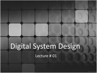
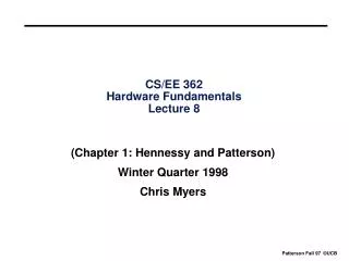
E 0 Q Q D R 1 Clock Q Figure 10.1 A flip-flop with an enable input
LIBRARY ieee ; USE ieee.std_logic_1164.all ; ENTITY rege IS PORT ( R, Resetn, E, Clock : IN STD_LOGIC ; Q : BUFFER STD_LOGIC ) ; END rege ; ARCHITECTURE Behavior OF rege IS BEGIN PROCESS ( Resetn, Clock ) BEGIN IF Resetn = '0' THEN Q <= '0' ; ELSIF Clock'EVENT AND Clock = '1' THEN IF E = '1' THEN Q <= R ; ELSE Q <= Q ; END IF ; END IF ; END PROCESS ; END Behavior ; Figure 10.2 VHDL code for a D flip-flop with an enable input
LIBRARY ieee ; USE ieee.std_logic_1164.all ; ENTITY regne IS GENERIC ( N : INTEGER := 4 ) ; PORT ( R : IN STD_LOGIC_VECTOR(N-1 DOWNTO 0) ; Resetn : IN STD_LOGIC ; E, Clock : IN STD_LOGIC ; Q : OUT STD_LOGIC_VECTOR(N-1 DOWNTO 0) ) ; END regne ; ARCHITECTURE Behavior OF regne IS BEGIN PROCESS ( Resetn, Clock ) BEGIN IF Resetn = '0' THEN Q <= (OTHERS => '0') ; ELSIF Clock'EVENT AND Clock = '1' THEN IF E = '1' THEN Q <= R ; END IF ; END IF ; END PROCESS ; END Behavior ; Figure 10.3 VHDL code for an n-bit register with an enable input
LIBRARY ieee ; USE ieee.std_logic_1164.all ; -- right-to-left shift register with parallel load and enable ENTITY shiftlne IS GENERIC ( N : INTEGER := 4 ) ; PORT( R : IN STD_LOGIC_VECTOR(N-1 DOWNTO 0) ; L, E, w : IN STD_LOGIC ; Clock : IN STD_LOGIC ; Q : BUFFER STD_LOGIC_VECTOR(N-1 DOWNTO 0) ) ; END shiftlne ; ARCHITECTURE Behavior OF shiftlne IS BEGIN PROCESS BEGIN … con’t Figure 10.4a Code for a right-to-left shift register with an enable input
… con’t WAIT UNTIL Clock'EVENT AND Clock = '1' ; IF E = '1' THEN IF L = '1' THEN Q <= R ; ELSE Q(0) <= w ; Genbits: FOR i IN 1 TO N-1 LOOP Q(i) <= Q(i-1) ; END LOOP ; END IF ; END IF ; END PROCESS ; END Behavior ; Figure 10.4b Code for a right-to-left shift register with an enable input (con’t)
LIBRARY ieee ; USE ieee.std_logic_1164.all ; PACKAGE components IS -- 2-to-1 multiplexer COMPONENT mux2to1 PORT ( w0, w1 : IN STD_LOGIC ; s : IN STD_LOGIC ; f : OUT STD_LOGIC ) ; END COMPONENT ; -- D flip-flop with 2-to-1 multiplexer connected to D COMPONENT muxdff PORT ( D0, D1, Sel, Clock : IN STD_LOGIC ; Q : OUT STD_LOGIC ) ; END COMPONENT ; -- n-bit register with enable COMPONENT regne GENERIC ( N : INTEGER := 4 ) ; PORT ( R : IN STD_LOGIC_VECTOR(N-1 DOWNTO 0) ; Resetn : IN STD_LOGIC ; E, Clock : IN STD_LOGIC ; Q : OUT STD_LOGIC_VECTOR(N-1 DOWNTO 0) ) ; END COMPONENT ; … con’t Figure 10.5a Component declaration statements for building blocks
… con’t -- n-bit right-to-left shift register with parallel load and enable COMPONENT shiftlne GENERIC ( N : INTEGER := 4 ) ; PORT ( R : IN STD_LOGIC_VECTOR(N-1 DOWNTO 0) ; L, E, w : IN STD_LOGIC ; Clock : IN STD_LOGIC ; Q : BUFFER STD_LOGIC_VECTOR(N-1 DOWNTO 0) ) ; END COMPONENT ; -- n-bit left-to-right shift register with parallel load and enable COMPONENT shiftrne GENERIC ( N : INTEGER := 4 ) ; PORT ( R : IN STD_LOGIC_VECTOR(N-1 DOWNTO 0) ; L, E, w : IN STD_LOGIC ; Clock : IN STD_LOGIC ; Q : BUFFER STD_LOGIC_VECTOR(N-1 DOWNTO 0) ) ; END COMPONENT ; … con’t Figure 10.5b Component declaration statements for building blocks (con’t)
… con’t -- up-counter that counts from 0 to modulus-1 COMPONENT upcount GENERIC ( modulus : INTEGER := 8 ) ; PORT ( Resetn : IN STD_LOGIC ; Clock, E, L : IN STD_LOGIC ; R : IN INTEGER RANGE 0 TO modulus-1 ; Q : BUFFER INTEGER RANGE 0 TO modulus-1 ) ; END COMPONENT ; -- down-counter that counts from modulus-1 down to 0 COMPONENT downcnt GENERIC ( modulus : INTEGER := 8 ) ; PORT ( Clock, E, L : IN STD_LOGIC ; Q : BUFFER INTEGER RANGE 0 TO modulus-1 ) ; END COMPONENT ; END components ; Figure 10.5c Component declaration statements for building blocks (con’t)
Static Random Access Memory • SRAM is used when a large amount of data needs to be stored. • SRAM block is 2-dimensional array of SRAM cells where each cell stores 1-bit. • To store m elements of n-bits, the aspect ratio of the SRAM array would be mn.
Sel Data Data Figure 10.6 An SRAM cell
Data Data 1 0 Sel 0 Sel 1 Figure 10.7 A 2 x 2 array of SRAM cells
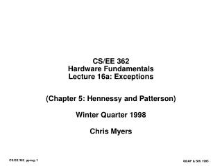
d d d Data inputs n – 1 n – 2 0 Write Sel 0 Sel 1 Sel a 2 0 decoder a 1 m Address -to-2 a m m – 1 Sel m 2 ” 1 Read q q q Data outputs n – 1 n – 2 0 Figure 10.8 A 2mxn SRAM block
B = 0 ; while A 0 do a = 1 if then 0 B = B + 1 ; End if; A Right-shift ; End while; Figure 10.9 Pseudo-code for the bit counter
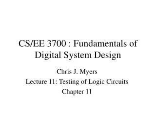
Reset S1 ¬ B 0 Load A 0 0 1 s s 1 S2 S3 Shift right A Done 1 ¬ A = 0 ? B B + 1 0 0 a 0 1 Figure 10.10 ASM chart for the bit counter
0 Data log n n 2 w 0 LB L L Counter LA EB E Shift E EA Clock log n A 2 n z B a 0 Figure 10.11 Data path for the bit counter
Reset S1 , LB EB EA 0 0 1 0 1 LA s s 1 S2 S3 Done EA 1 z EB 0 0 a 0 1 Figure 10.12 ASM chart for the bit counter control circuit
LIBRARY ieee ; USE ieee.std_logic_1164.all ; LIBRARY work ; USE work.components.shiftrne ; ENTITY bitcount IS PORT( Clock, Resetn : IN STD_LOGIC ; LA, s : IN STD_LOGIC ; Data : IN STD_LOGIC_VECTOR(7 DOWNTO 0) ; B : BUFFER INTEGER RANGE 0 to 8 ; Done : OUT STD_LOGIC ) ; END bitcount ; ARCHITECTURE Behavior OF bitcount IS TYPE State_type IS ( S1, S2, S3 ) ; SIGNAL y : State_type ; SIGNAL A : STD_LOGIC_VECTOR(7 DOWNTO 0) ; SIGNAL z, EA, LB, EB, low : STD_LOGIC ; BEGIN FSM_transitions: PROCESS ( Resetn, Clock ) BEGIN IF Resetn = '0' THEN y <= S1 ; … con’t Figure 10.13a VHDL code for the bit-counting circuit
ELSIF (Clock'EVENT AND Clock = '1') THEN CASE y IS WHEN S1 => IF s = '0' THEN y <= S1 ; ELSE y <= S2 ; END IF ; WHEN S2 => IF z = '0' THEN y <= S2 ; ELSE y <= S3 ; END IF ; WHEN S3 => IF s = '1' THEN y <= S3 ; ELSE y <= S1 ; END IF ; END CASE ; END IF ; END PROCESS ; FSM_outputs: PROCESS ( y, s, A(0), z ) BEGIN EA <= '0' ; LB <= '0' ; EB <= '0' ; Done <= '0' ; CASE y IS WHEN S1 => LB <= '1' ; EB <= '1' ; IF s = '0' AND LA = '1' THEN EA <= '1' ; ELSE EA <= '0' ; END IF ; WHEN S2 => EA <= '1' ; IF A(0) = '1' THEN EB <= '1' ; ELSE EB <= '0' ; END IF ; … con’t Figure 10.13b VHDL code for the bit-counting circuit (con’t)
WHEN S3 => Done <= '1' ; END CASE ; END PROCESS ; -- The datapath circuit is described below upcount: PROCESS ( Resetn, Clock ) BEGIN IF Resetn = '0' THEN B <= 0 ; ELSIF (Clock'EVENT AND Clock = '1') THEN IF EB = '1' THEN IF LB = '1' THEN B <= 0 ; ELSE B <= B + 1 ; END IF ; END IF ; END IF; END PROCESS; low <= '0' ; ShiftA: shiftrne GENERIC MAP ( N => 8 ) PORT MAP ( Data, LA, EA, low, Clock, A ) ; z <= '1' WHEN A = "00000000" ELSE '0' ; END Behavior ; Figure 10.13c VHDL code for the bit-counting circuit (con’t)
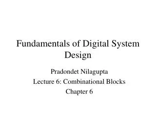
Figure 10.14 Simulation results for the bit-counting circuit
P = 0 ; – i = 0 n 1 for to do b = 1 if then i P = P + A ; end if; A Left-shift ; end for; Decimal Binary 13 1 1 0 1 Multiplicand 11 1 0 1 1 Multiplier ´ ´ 13 1 1 0 1 13 1 1 0 1 0 0 0 0 143 1 1 0 1 1 0 0 0 1 1 1 1 Product (a) Manual method (b) Pseudo-code Figure 10.15 An algorithm for multiplication
Reset S1 ¬ P 0 Load A Load B 0 0 1 s s 1 S2 S3 Shift left A , Shift right B Done 1 ¬ B = 0 ? P P + A 0 0 b 0 1 Figure 10.16 ASM chart for the multiplier
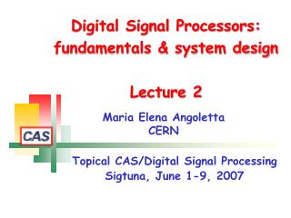
LA 0 DataA LB DataB n n n L L Shift-left Shift-right EA EB E E register register A B Clock n 2n + z b Sum 0 0 2n 2n 1 0 Psel 2n DataP EP E Register 2n P Figure 10.17 Datapath circuit for the multiplier
Reset S1 , = 0 EP Psel 0 0 0 LB LA s 1 1 1 EB EA 0 1 s S3 S2 , , = 1 EAEB Done Psel 1 z EP 0 0 b 0 1 Figure 10.18 ASM chart for the multiplier control circuit
LIBRARY ieee ; USE ieee.std_logic_1164.all ; USE ieee.std_logic_unsigned.all ; USE work.components.all ; ENTITY multiply IS GENERIC ( N : INTEGER := 8; NN : INTEGER := 16 ) ; PORT ( Clock : IN STD_LOGIC ; Resetn : IN STD_LOGIC ; LA, LB, s : IN STD_LOGIC ; DataA : IN STD_LOGIC_VECTOR(N-1 DOWNTO 0) ; DataB : IN STD_LOGIC_VECTOR(N-1 DOWNTO 0) ; P : BUFFER STD_LOGIC_VECTOR(NN-1 DOWNTO 0) ; Done : OUT STD_LOGIC ) ; END multiply ; ARCHITECTURE Behavior OF multiply IS TYPE State_type IS ( S1, S2, S3 ) ; SIGNAL y : State_type ; SIGNAL Psel, z, EA, EB, EP, Zero : STD_LOGIC ; SIGNAL B, N_Zeros : STD_LOGIC_VECTOR(N-1 DOWNTO 0) ; SIGNAL A, Ain, DataP, Sum : STD_LOGIC_VECTOR(NN-1 DOWNTO 0) ; BEGIN … con’t Figure 10.19a VHDL code for the multiplier circuit
FSM_transitions: PROCESS ( Resetn, Clock ) BEGIN IF Resetn = '0' THEN y <= S1 ; ELSIF (Clock'EVENT AND Clock = '1') THEN CASE y IS WHEN S1 => IF s = '0' THEN y <= S1 ; ELSE y <= S2 ; END IF ; WHEN S2 => IF z = '0' THEN y <= S2 ; ELSE y <= S3 ; END IF ; WHEN S3 => IF s = '1' THEN y <= S3 ; ELSE y <= S1 ; END IF ; END CASE ; END IF ; END PROCESS ; FSM_outputs: PROCESS ( y, s, LA, LB, B(0) ) BEGIN EP <= '0' ; EA <= '0' ; EB <= '0' ; Done <= '0' ; Psel <= '0'; CASE y IS WHEN S1 => EP <= '1' ; IF s = '0' AND LA = '1' THEN EA <= '1' ; ELSE EA <= '0' ; END IF ; IF s = '0' AND LB = '1' THEN EB <= '1' ; … con’t Figure 10.19b VHDL code for the multiplier circuit (con’t)
ELSE EB <= '0' ; END IF ; WHEN S2 => EA <= '1' ; EB <= '1' ; Psel <= '1' ; IF B(0) = '1' THEN EP <= '1' ; ELSE EP <= '0' ; END IF ; WHEN S3 => Done <= '1' ; END CASE ; END PROCESS ; -- Define the datapath circuit Zero <= '0' ; N_Zeros <= (OTHERS => '0' ) ; Ain <= N_Zeros & DataA ; ShiftA: shiftlne GENERIC MAP ( N => NN ) PORT MAP ( Ain, LA, EA, Zero, Clock, A ) ; ShiftB: shiftrne GENERIC MAP ( N => N ) PORT MAP ( DataB, LB, EB, Zero, Clock, B ) ; z <= '1' WHEN B = N_Zeros ELSE '0' ; Sum <= A + P ; -- Define the 2n 2-to-1 multiplexers for DataP GenMUX: FOR i IN 0 TO NN-1 GENERATE Muxi: mux2to1 PORT MAP ( Zero, Sum(i), Psel, DataP(i) ) ; END GENERATE; RegP: regne GENERIC MAP ( N => NN ) PORT MAP ( DataP, Resetn, EP, Clock, P ) ; END Behavior ; Figure 10.19c VHDL code for the multiplier circuit (con’t)
15 Q 00001111 9 140 A 1001 100 01100 B 9 1001 50 10 001 45 10 01 10000 5 1001 1110 1001 (a) An example using decimal numbers R 101 (b) Using binary numbers R = 0 ; i = 0 n – 1 for to do R A Left-shift ; if R B then q = 1 ; i – R = R B ; else q = 0 ; i end if; end for; (c) Pseudo-code Figure 10.21 An algorithm for division
Reset S1 ¬ , ¬ R 0 C n 1 – Load A Load B 0 1 s 0 1 S2 s Shift left R||A S4 S3 ¬ C C ” 1 Done 0 1 ³ R B ? Shift 1 into Q Shift 0 into Q ¬ R R B – 1 0 C = 0 ? Figure 10.22 ASM chart for the divider
0 n DataB DataA LA EB Rsel 1 0 n n LR L E L Left-shift Left-shift Register E w ER EA register register E n n n B a n ” 1 A EQ E Left-shift c c w 1 out in register + n n Clock Q R Figure 10.23 Datapath circuit for the divider
Reset S1 EA , = 0 Rsel LR, ER, LC, EC 1 0 1 0 LA s S2 ER, EA S3 , = 1 EC EQ, Rsel 0 1 0 c s out 1 S4 Done LR, ER 1 0 z Figure 10.24 ASM chart for the divider control circuit
B 1001 10001100 A rr Clock cycle R A/ Q 0 Load A, B 0 0 0 0 0 0 0 0 0 0 1 1 0 0 0 0 1 Shift left 0 0 0 0 0 0 1 0 0 1 1 0 0 0 0 0 0 0 , ¬ 0 0 0 0 0 1 0 0 1 1 0 0 0 0 0 0 0 Shift left Q 0 1 0 , 0 0 0 0 0 0 1 0 0 0 1 1 0 0 0 0 0 ¬ 2 Shift left Q 0 0 , 0 0 0 0 0 1 0 0 0 1 1 0 0 0 0 0 0 ¬ 3 Shift left Q 0 0 , ¬ 0 0 0 0 1 0 0 0 1 1 0 0 0 0 0 0 0 Shift left Q 0 4 0 , ¬ 0 0 0 0 1 0 0 0 1 0 0 0 0 0 0 0 1 Subtract Q 1 5 0 , ¬ 6 0 0 0 0 1 0 0 0 0 0 0 0 0 0 0 1 1 Subtract Q 1 0 , ¬ Subtract Q 1 7 0 0 1 1 0 0 0 1 1 1 0 0 0 1 0 0 0 0 , ¬ Subtract Q 1 8 0 0 0 1 0 1 0 0 0 0 1 1 1 1 0 0 0 0 Figure 10.25 An example of division using n = 8 clock cycles
Reset S1 , , , = 0 LC EC ER Rsel EA 1 1 0 s LA 0 EA, ER0 LR S2 , , , ER ER0 EA = 1 Rsel 0 0 1 c s out 1 S3 LR EC Done 1 0 z Figure 10.26 An example of division using n = 8 clock cycles
DataB LA DataA EB n n L E Left-shift Register EA w E register Clock n n B c c 1 out in + n 0 n Rsel 1 0 ER0 rr LR L 0 0 0 Left-shift ER w E Q D register 1 q n – 1 Q n n n – 1 ¼ r r n – 2 0 n n Q R Figure 10.27 Datapath circuit for the enhanced divider
LIBRARY ieee; USE ieee.std_logic_1164.all; USE ieee.std_logic_unsigned.all ; USE work.components.all ; ENTITY divider IS GENERIC ( N : INTEGER := 8 ) ; PORT ( Clock : IN STD_LOGIC ; Resetn : IN STD_LOGIC ; s, LA, EB : IN STD_LOGIC ; DataA : IN STD_LOGIC_VECTOR(N-1 DOWNTO 0) ; DataB : IN STD_LOGIC_VECTOR(N-1 DOWNTO 0) ; R, Q : BUFFER STD_LOGIC_VECTOR(N-1 DOWNTO 0) ; Done : OUT STD_LOGIC ) ; END divider ; ARCHITECTURE Behavior OF divider IS TYPE State_type IS ( S1, S2, S3 ) ; SIGNAL y : State_type ; SIGNAL Zero, Cout, z : STD_LOGIC ; SIGNAL EA, Rsel, LR, ER, ER0, LC, EC, R0 : STD_LOGIC ; SIGNAL A, B, DataR : STD_LOGIC_VECTOR(N-1 DOWNTO 0) ; SIGNAL Sum : STD_LOGIC_VECTOR(N DOWNTO 0) ; -- adder outputs SIGNAL Count : INTEGER RANGE 0 TO N-1 ; … con’t Figure 10.28a VHDL code for the divider circuit
BEGIN FSM_transitions: PROCESS ( Resetn, Clock ) BEGIN IF Resetn = '0' THEN y <= S1 ; ELSIF (Clock'EVENT AND Clock = '1') THEN CASE y IS WHEN S1 => IF s = '0' THEN y <= S1 ; ELSE y <= S2 ; END IF ; WHEN S2 => IF z = '0' THEN y <= S2 ; ELSE y <= S3 ; END IF ; WHEN S3 => IF s = '1' THEN y <= S3 ; ELSE y <= S1 ; END IF ; END CASE ; END IF ; END PROCESS ; FSM_outputs: PROCESS ( s, y, Cout, z ) BEGIN LR <= '0' ; ER <= '0' ; ER0 <= '0' ; LC <= '0' ; EC <= '0' ; EA <= '0' ; Done <= '0' ; Rsel <= '0' ; CASE y IS WHEN S1 => … con’t Figure 10.28b VHDL code for the divider circuit (con’t)
LC <= '1' ; EC <= '1' ; ER <= '1' ; IF s = '0' THEN LR <= '1' ; IF LA = '1' THEN EA <= '1' ; ELSE EA <= '0' ; END IF ; ELSE EA <= '1' ; ER0 <= '1' ; END IF ; WHEN S2 => Rsel <= '1' ; ER <= '1' ; ER0 <= '1' ; EA <= '1' ; IF Cout = '1' THEN LR <= '1' ; ELSE LR <= '0' ; END IF ; IF z = '0' THEN EC <= '1' ; ELSE EC <= '0' ; END IF ; WHEN S3 => Done <= '1' ; END CASE ; END PROCESS ; -- define the datapath circuit Zero <= '0' ; RegB: regne GENERIC MAP ( N => N ) PORT MAP ( DataB, Resetn, EB, Clock, B ) ; ShiftR: shiftlne GENERIC MAP ( N => N ) PORT MAP ( DataR, LR, ER, R0, Clock, R ) ; … con’t Figure 10.28c VHDL code for the divider circuit (con’t)
FF_R0: muxdff PORT MAP ( Zero, A(N-1), ER0, Clock, R0 ) ; ShiftA: shiftlne GENERIC MAP ( N => N ) PORT MAP ( DataA, LA, EA, Cout, Clock, A ) ; Q <= A ; Counter: downcnt GENERIC MAP ( modulus => N ) PORT MAP ( Clock, EC, LC, Count ) ; z <= '1' WHEN Count = 0 ELSE '0' ; Sum <= R & R0 + (NOT B +1) ; Cout <= Sum(N) ; DataR <= (OTHERS => '0') WHEN Rsel = '0' ELSE Sum ; END Behavior ; Figure 10.28d VHDL code for the divider circuit (con’t)
= 0 Sum ; – i = k 1 for down to 0 do = +R ; Sum Sum i end for; = ÷ k M Sum ; (a) Pseudo-code Reset S1 Sum 0 ¬ , ¬ C k – 1 Load registers 0 s 1 S2 ¬ Sum Sum + R i ¬ C C – 1 0 0 C = 0 ? s 1 1 S3 S4 ¬ ¤ M Sum k Done (b) ASM chart Figure 10.30 An algorithm for finding the mean of k numbers
Figure 10.33 Schematic of the mean circuit with an SRAM block
Figure 10.34 Simulation results for the mean circuit using SRAM
– i = 0 k 2 for to do A = R ; i – j = i + 1 k 1 for to do B = R ; j B < A if then R = B ; i R = A ; j A = R ; i end if ; end for; end for; Figure 10.35 Pseudo-code for the sort operation
Reset S1 ¬ 0 C i Load registers 0 s 1 S2 ¬ , ¬ A R C C i j i S3 ¬ C C + 1 ¬ C C + 1 j j i i S4 ¬ B R j S5 S6 1 ¬ C C + 1 ¬ R A B < A ? j j j 0 S7 ¬ R B i S8 ¬ A R i 0 C = k – 1 ? j S9 0 1 Done s 1 1 0 C = k – 2 ? i Figure 10.36 ASM chart for the sort operation
DataIn ABmux n WrInit 0 1 n RData Rin Rin Rin Rin E E E E 0 1 2 3 R R R R 0 1 2 3 0 1 2 3 Imux ABData Ain Bin Rd E E n Clock DataOut < Bout 1 0 A B BltA Figure 10.37 A part of the datapath circuit for the sort operation