Multiplexed External Bus Interface (MEBIV3) Overview and Functional Description
160 likes | 289 Vues
This document provides a comprehensive overview of the Multiplexed External Bus Interface (MEBIV3) developed by Prof. Mahendra B. Salunke from SITS, Pune. It includes a detailed block diagram, features such as external bus controllers with multiple 8-bit ports, and various operational modes, including normal and special modes for debugging and factory testing. The MEBIV3 allows the interfacing of 16-bit and 8-bit external memory and devices, with control registers for configuring various settings, memory mapping, and handling of external signals.

Multiplexed External Bus Interface (MEBIV3) Overview and Functional Description
E N D
Presentation Transcript
Multiplexed External Bus Interface-MEBIV3 By: Prof. Mahendra B. Salunke Asst. Prof., Department of Computer Engg., SITS, Pune-41 Email: msalunke@gmail.com URL: microsig.webs.com
Contents • MEBIV3
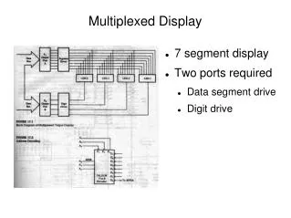
Features • External bus controller with four 8-bit ports A,B, E, and K • Data and data direction registers for ports A, B, E, and K when used as general-purpose I/O • Control register to enable/disable alternate functions on ports E and K • Mode control register • Control register to enable/disable pull-ups on ports A, B, E, and K • Control register to enable/disable reduced output drive on ports A, B, E, and K • Control register to configure external clock behavior • Control register to configure IRQ pin operation • Logic to capture and synchronize external interrupt pin inputs
Modes of Operations • Normal expanded wide mode • Ports A and B are configured as a 16-bit multiplexed address and data bus and port E provides bus control and status signals. • This mode allows 16-bit external memory and peripheral devices to be interfaced to the system. • Normal expanded narrow mode • Ports A and B are configured as a 16-bit address bus and port A is multiplexed with 8-bit data. • Port E provides bus control and status signals. This mode allows 8-bit external memory andperipheral devices to be interfaced to the system.
Modes Continued…. • Normal single-chip mode • There is no external expansion bus in this mode. • The processor program is executed from internal memory. Ports A, B, K, and most of E are available as general-purpose I/O. • Special single-chip mode • This mode is generally used for debugging single-chip operation, boot-strapping, or security related operations. • The active background mode is in control of CPU execution and BDM firmware is waiting for additional serial commands through the BKGD pin. • There is no external expansion bus after reset in this mode.
Modes Continued…. • Emulation expanded wide mode • Developers use this mode for emulation systems in which the users target application is normal expanded wide mode. • Emulation expanded narrow mode • Developers use this mode for emulation systems in which the users target application is normal expanded narrow mode.
Modes Continued…. • Special test mode • Ports A and B are configured as a 16-bit multiplexed address and data bus and port E provides bus control and status signals. • In special test mode, the write protection of many control bits is lifted so that they can be thoroughly tested without needing to go through reset. • Special peripheral mode • This mode is intended for Freescale Semiconductor factory testing of the system. • The CPU is inactive and an external (tester) bus master drives address, data, and bus control signals.
External Signals • the MEBI sub-block of the core interfaces directly with external system pins. • External System Pins Associated With MEBI • BKGD/MODC/TAGHI#, PA7/A15/D15/D7 thru PA0/A8/D8/D0, PB7/A7/D7 thru PB0/A0/D0, PE7/NOACC, PE6/IPIPE1/MODB/CLKTO, PE5/IPIPE0/MODA, PE4/ECLK, PE3/LSTRB#/ TAGLO#, PE2/R/W#, PE1/IRQ#, PE0/XIRQ#, PK7/ECS#, PK6/XCS#, PK5/X19 thru PK0/X14
External Signals • Most interfacing with the interrupt sub-block is done within the core. • However, the interrupt does receive direct input from the multiplexed external bus interface (MEBI) sub-block of the core for the IRQ and XIRQ pin data.
MEBI Memory Map • Port A Data Register (PORTA) 0x0000 • Port B Data Register (PORTB) 0x0001 • Data Direction Register A (DDRA) 0x0002 • Data Direction Register B (DDRB) 0x0003 • Reserved 0x0004 to 0x0007 • Port E Data Register (PORTE) 0x0008 • Data Direction Register E (DDRE) 0x0009 • Port E Assignment Register (PEAR) 0x000A • Mode Register (MODE) 0x000B
Memory Map Continued…. • Pull-Up Control Register (PUCR) 0x000C • Reduced Drive Register (RDRIV) 0x000D • External Bus Interface Control Register (EBICTL) 0x000E • Reserved 0x000F • IRQ Control Register (IRQCR) 0x001E • Port K Data Register (PORTK) 0x0032 • Data Direction Register K (DDRK) 0x0033 Reserved registers are having read access and remaining registers are having R/W access in R/W
Functional Description • Detecting Access Type from External Signals • The external signals LSTRB, R/W, and AB0 indicate the type of bus access that is taking place. • Stretched Bus Cycles • In order to allow fast internal bus cycles to coexist in a system with slower external memory resources, the HCS12 supports the concept of stretched bus cycles.
Functional Description • Modes of Operation • The operating mode out of reset is determined by the states of the MODC, MODB, and MODA pins during reset • Internal Visibility • Internal visibility is available when the MCU is operating in expanded wide modes or emulation narrow mode. • It is not available in single-chip, peripheral or normal expanded narrow modes. Internal visibility is enabled by setting the IVIS bit in the MODE register.
Functional Description • Low-Power Options • Operation in Run Mode • The MEBI does not contain any options for reducing power in run mode; • Operation in Wait Mode • The MEBI does not contain any options for reducing power in wait mode. • Operation in Stop Mode • The MEBI will cease to function after execution of a CPU STOP instruction.
Happy Learning Contact Details: Email: msalunke@gmail.com URL: microsig.webs.com