Download

1 / 45
450 likes | 691 Vues
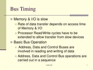
8088 CPU External Pins, Timing, and IBM PC BUS. 四川大学计算机学院 李征 Tel: 13882153765 Oicq:1340915 Email: lizheng@cs.scu.edu.cn. 8088 CPU External Pins, Timing, and IBM PC BUS. Crucial Content Pin functions of 8088 Minimum Mode Bus generating of 8088 Minimum Mode Timing of 8088 Minimum Mode

E N D
8088 CPU External Pins, Timing, and IBM PCBUS 四川大学计算机学院 李征 Tel: 13882153765 Oicq:1340915 Email: lizheng@cs.scu.edu.cn
8088 CPU External Pins, Timing, and IBM PCBUS • Crucial Content • Pin functions of 8088 Minimum Mode • Bus generating of 8088 Minimum Mode • Timing of 8088 Minimum Mode • IBM PCBus
GND AD14 AD13 AD12 AD11 AD10 AD9 AD8 AD7 AD6 AD5 AD4 AD3 AD2 AD1 AD0 NMI INTR CLK GND 1 2 3 4 5 6 7 8 9 10 11 12 13 14 15 16 17 18 19 20 40 39 38 37 36 35 34 33 32 31 30 29 28 27 26 25 24 23 22 21 VCC AD15 A16/ S3 A17 / S4 A18 / S5 A19 / S6 BHE*/S7 MN / MX* RD* HOLD (RQ0*/ GT0*) HLDA (RQ1* /GT1*) WR* (LOCK*) M / IO* ( S2*) DT / R* ( S1*) DEN ( S0) ALE (QS0) INTA (QS1) TEST* READY RESET 8086 (1)Pins of 8086
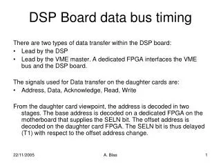
GND A14 A13 A12 A11 A10 A9 A8 AD7 AD6 AD5 AD4 AD3 AD2 AD1 AD0 NMI INTR CLK GND 1 2 3 4 5 6 7 8 9 10 11 12 13 14 15 16 17 18 19 20 40 39 38 37 36 35 34 33 32 31 30 29 28 27 26 25 24 23 22 21 VCC A15 A16 / S3 A17 / S4 A18 / S5 A19 / S6 SS0* (HIGH) MN / MX* RD* HOLD (RQ0*/ GT0*) HLDA (RQ1* /GT1*) WR* (LOCK*) M */ IO ( S2*) DT / R* ( S1*) DEN ( S0) ALE (QS0) INTA (QS1) TEST* READY RESET 8088 (2)Pins of 8088
(2)8088的引脚图 • Naming Tradition of Signal: • MX or MX* represents that this signal is valid as 0.
(3) 8088的两种组态模式 • There are two operation modes in 8086/8088. • Minimum Mode • Used for small system • 8088 generate system bus with pins directly • Maximum Mode • Used for large system, and 8087 can be included • System bus is generated by 8088and System Bus Controller 8288
(3) How to decide operation mode of 8088 • Input signal from MN/MX*pin decide the CPU operation mode • Inputting 1 to MN/MX*for Minimum Mode • Inputting 0 to MN/MX*for Maximum Mode
(4)8088 Pins in Minimum Mode • Data and Address Pins • Reading and WritingPins • Interrupt Requesting and Accepting Pins • DMA Requesting and Accepting Pins • Other Pins
1. Data and Address Pins • AD7~AD0(Address/Data)(8088) • Multiplexed (分时复用) pins, Bidirectional, Three-State • Multiplexed pin has different meanings at different clock cycles. • The purpose of multiplexed pin is to decrease pin numbers.
1. Data and Address Pins • Bidirectional Pin: There are two possible signal directions on bidirectional pin. • Three-State Pin: There are three possible states on Three-State Pin, which are 0, 1, and blocking state.
1. Data and Address Pins—Three-State • Three-State of pins is realized by three-state output gate. • Functions of Three-State Output Gate:power amplification, breakable connection • Chip pin is connected with system bus through three-state output gate.
if T=0: Blocking State if T=1: F = A A F A F A F A F T T T Represent ‘Not’ T 1. Data and Address Pins—Three-State Three State, One Direction Three-State output gate Inside Outside
A B T OE* 1. Data and Address Pins—Three-State Bidirectional Three-State Gate Three State, Two Direction Inside Outside OE*=0,connected T=1 A→B T=0 A←B OE*=1,blocked
1. Data and Address Pins • Thinking: • 1)Whether data or address signal is bidirectional? • 2)Why is there three states at chip pin?
1. Data and Address Pins • AD7~AD0(Address/Data) (8088) • Timing: • In bus operation, for memory or interface, these pins output lowest 8-bit address signal (A7~A0) at 1st CLK cycle. • These pins transfer 8-bit data signal at other CLK cycles in bus operation.
1. Data and Address Pins • A15~A8(Address) • Address Pins, Output, Three-State
1. Data and Address Pins • A19/S6~A16/S3(Address/Status) • Multiplexed Pins, Output, Three-State • In memory operation, these pins output highest 4-bit address (A19~A16) at 1st CLK cycle. • In port operation, these pins output 0 (invalid) at 1st CLK cycle. (Why? 16-bit address for I/O ports) • At other CLK cycles of bus operation, they output status signal (S6~S3 ).
1. Data and Address Pins S6 is always 0; S5is the ‘IF’ flag state; S4and S3represent which segment register is used in current bus operation,00 for ES,01for SS,10for CS,11for DS. These four pins are blocked in DMA cycles.
2. Reading or Writing Control Pins • ALE(Address Latch Enable) • Output, Three-State, 1 is valid • If ALE=1,AD7~AD0and A19/S6~A16/S3are transfer address signal. • Because address only appear on these pins temporarily, system bus can latch them in register by ALE signal.
D Q C Q 上升沿锁存 2. Reading or Writing Control Pins • Address Latching 20个触发器构成的1个存储单元可以锁存全部20位物理地址 AX 由晶振片产生,经过整形、分频后,提供给各芯片同步操作的基准信号,系统中的“时钟周期”即为此信号的周期 ALE CLK
2. Reading or Writing Control Pins • IO/M*(Input and Output/Memory) • Output, Three-State • If IO/M*=1, CPU accesses I/O port, and A15~A0 output I/O port address. • If IO/M*=0, CPU accesses memory cell, and A19~A0 output memory cell address.
2. Reading or Writing Control Pins • WR*(Write) • Output, Three-State, 0 is valid • If WR* is valid, CPU is writing data into memory cell or I/O port.
2. Reading or Writing Control Pins • RD*(Read) • Output, Three-State, 0 is valid • When RD* is valid, CPU is reading data from memory cell or I/O port.
2. Reading or Writing Control Pins • IO/M*, WR*, and RD*are basic control signals • They distinguish 4 basic bus operations.
I/O读 I/O写 存储器读 存储器写 2. Reading or Writing Control Pins—(IBM-PCBus)
2. Reading or Writing Control Pins • READY • Input, 1 is valid • In bus operation,8088 CPU will test this pin at descending edge (1rt edge) of 3rd CLK cycle. • If READY=1, bus operation of CPU enter 4th CLK cycle. • If READY=0,bus operation of CPU will insert waiting cycle (Tw) between 3rd and 4th CLK cycles. • CPU will test this pin in waiting cycle too. If READY is valid, bus operation enter 4th CLK cycle. Or else, new waiting cycle is inserted.
2. Reading or Writing Control Pins • DEN*(Data Enable) • Output, Three-State, 0 is valid • If DEN* is valid, CPU begins data transfer on data bus. • This signal can be used to drive data bus.
2. Reading or Writing Control Pins • DT/R*(Data Transmit/Receive) • Output, Three-State • This signal represent the direction of data transfer on bus. • If DT/R*=1, CPU sends data to bus. • If DT/R*=0, CPU receives data from bus.
2. Reading or Writing Control Pins • SS0*(System Status 0) • 8088 pin, Output (Only valid in Minimum Mode) • SS0*, IO/M*, and DT/R*can represent 8 different bus operation in 8088 minimum mode: 1. Instruction Read 5. Interrupt Accept 2. Memory Read 6. I/ORead 3. Memory Write 7. I/OWrite 4. Passive 8. Halt
3. Interrupt Request and Acknowledge Pins • INTR(Interrupt Request, Maskable) • Input, 1 is valid • If INTR=1, there is at least one device send interrupt request to CPU. • Maskable interrupt request can be blocked by IF flag. If IF=0, CPU will not accept any maskable interrupt requets.
3. Interrupt Request and Acknowledge Pins • INTA*(Interrupt Acknowledge) • Output, 0 is valid • If INTA* is valid, the request from INTR has been accepted by CPU, and the timing will enter interrupt accept cycle.
3. Interrupt Request and Acknowledge Pins NMI(Non-Maskable Interrupt) • Input, Ascending Edge is valid • If NMI is valid, there is non-maskable interrupt request to CPU. • The request from NMI can not be blocked in CPU.
3. Interrupt Request and Acknowledge Pins • Maskable interrupt is often used for data exchange between CPU and I/O devices. • Non-Maskable interrupt is often used for system failure.
4. DMA Request and Acknowledge Pins • HOLD • Input, 1 is valid • If HOLD is valid, there is at least one device requests for system bus control. • In most situations, system bus is controlled by CPU. However, other DMA devices can request bus control from CPU.
4. DMA Request and Acknowledge Pins • HLDA(HOLD Acknowledge) • Output, 1 is valid • If HLDA is valid, request from HOLD has been accepted, CPU has release system bus, and most pins of CPU is at blocking state. • In the mean time, DMA interface can use system bus without disturbances. • When HOLD is invalid, CPU cancels HLDA, and obtain the bus control again.
5. Other Pins • RESET • Input, 1 is valid • If RESET is valid, CPU enter initial state and does not work. After RESET is invalid again, CPU will work again. • After 8088/86resetting CS=FFFFH、IP=0000H, Rebooting Address: FFFF0H
5. Other Pins • CLK(Clock) • Clock Input • Reference of CPU and system bus timing. • Standard 8088 clock frequency is 5MHz. • 8088 in IBM PC/XTuses 4.77MHzclock, the CLK cycle is about 210ns. • CLK is provided by clock generator 8284.
5. Other Pins • Vcc • Power Input for CPU, +5V • GND • Ground input for CPU,ground reference of CPU
5. Other Pins • MN/MX*(Minimum/Maximum) • Operation Mode Choice, Input • If this pin is 1,8088 is at minimum mode. Otherwise, 8088is at maximum mode.
5. Other Pins • TEST* • Input, 0 is valid • This pin is used for synchronization between 8088 and 8087. • When CPUexecute WAITinstruction, it will test this pin in every CLK cycle. • If TEST* is invalid, CPU will continue this pin testing.Otherwise, CPU will execute following instructions.
(4)Summery for Pins in 8088Minimum Mode • Crucial properties of Pins: ⑴ Function ⑵ Direction ⑶ Valid Signal ⑷ Three-State (5) Multiplexed
(4)Summery for Pins in 8088Minimum Mode Three pin types in CPU: • 8-bit Data Pins:D0~D7 • 20-bit Address Pins:A0~A19 • Control Pins: • ALE、IO/M*、WR*、RD*、READY • INTR、INTA*、NMI,HOLD、HLDA • RESET、CLK、Vcc、GND
(4)Summery for Pins in 8088Minimum Mode • Questions: • How do these CPU pins connect with other chips? • System Bus Generating • How can these signals on CPU pins be transferred orderly? • System Bus Timing
系统总线信号 MN/MX* IO/M* RD* WR* +5V IO/M* RD* WR* A19/S6~A16/S3 8282 A19~A16 OE* STB 8088 A15~A8 8282 A15~A8 OE* STB A7~A0 AD7~AD0 8282 OE* STB ALE 8286 D7~D0 DT/R* DEN* T OE* (5)System Bus Generating in Minimum Mode