Bus Timing
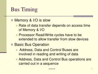
Bus Timing. Memory & I/O is slow Rate of data transfer depends on access time of Memory & I/O Processor Read/Write cycles have to be extended to allow transfer from slow devices Basic Bus Operation Address, Data and Control Buses are involved in reading and writing of data

Bus Timing
E N D
Presentation Transcript
Bus Timing • Memory & I/O is slow • Rate of data transfer depends on access time of Memory & I/O • Processor Read/Write cycles have to be extended to allow transfer from slow devices • Basic Bus Operation • Address, Data and Control Buses are involved in reading and writing of data • Address, Data and Control Bus operations are carried out in a sequence Lecture 04
Bus Timing • 8086/8088 use the Memory/IO in periods called Bus Cycles • Each Bus Cycle equals 4 system clocking periods (T states) • Pentium has 2 T state Bus cycle • At 5 MHz, one Bus cycle is completed at 0.8 sec or 800 nsec • Processor can read/write at a max. rate of 1.25 million times a sec. Lecture 04
Bus Timing • With internal queue processor can execute 2.5 million instructions per sec. [MIPS] in bursts • Pentium operates at much higher rates due to higher clock rates, shorter Bus cycle and internal queuing Lecture 04
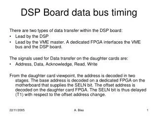
Bus Timing T1 Clock • Address of the Memory/IO is issued via the Address/Data Multiplexed Bus • Following Signals are also issued • ALE Address Latch Enable signal • DT/R* Data Transmit/Receive signal • IO/M* IO/Memory signal Lecture 04
Bus Timing T2 & T3 Clocks • RD* or WR* Read or Write Signal is issued • Incase of Write the Data to be written also appears on the Data Bus • DEN* Data Bus Enable signal is issued • READY signal is sampled at the end of T2 • If READY is low T3 becomes a Wait State TW • READY is again sampled in the middle of Wait State • If the Bus Cycle is Read Cycle, Data Bus is sampled at the end of T3 Lecture 04
Bus Timings T4 Clock • All Bus signals are deactivated in preparation for the next Bus Cycle • During a Read Cycle the processor continues to sample the Data Bus during T4 cycle • During a Write Cycle the trailing edge of the Write signal transfers the data to Memory or IO Lecture 04