BUS Timing
BUS Timing. BREY-P.322. Bus Timing. There are three types of buses of 8086 and 8088 address, data and control– function exactly the same way as those of any other microprocessor.

BUS Timing
E N D
Presentation Transcript
BUS Timing BREY-P.322
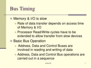
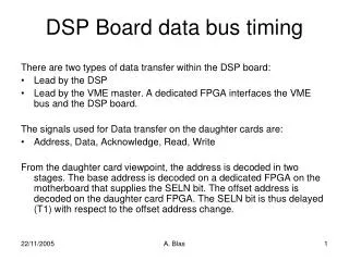
Bus Timing • There are three types of buses of 8086 and 8088address, data and control– function exactly the same way as those of any other microprocessor. • The 8086 and 8088 microprocessors use the memory and I/O in period are called bus cycle. Each bus cycle equal 4 system clocking period.
Basic Bus Operations • If data are written to the memory, the microprocessor outputs the memory address on the address bus, issue a write signal (WR) to memory (M/IO=1) or I/O (M/IO=0) . • If data are read from the memory, the microprocessor outputs the memory address on the address bus, issue a read (RD) memory signal, and accept the data via data bus.
WRITE BUS CYCLE --------------------------- ONE BUS CYCLE-------------------------------------- T1 T2 T3 T4 CLK ADDRESS Address/ Data WR VALID ADDRESS ADDRESS DATA WRITTEN TO MEMORY
READ BUS CYCLE --------------------------- ONE BUS CYCLE-------------------------------------- T1 T2 T3 T4 CLK ADDRESS Address/ Data RD VALID ADDRESS ADDRESS DATA FROM MEMORY
During T1: The address of memory or i/o location is sent out via the address bus and address/data bus connection (the address/data bus multiplexed and sometime contains memory addressing information or data). Control signal ALE, DT/R and IO/M (it indicate whether the address bus contains the memory address or i/o port number) • DT/R– data transmit or receive
During T2: microprocessor issues WR or RD signals, DEN (data bus enable), and in the case of write, the data to be written appear (come out) on the data bus. This clocking period is allowing the memory/ IO time to access data until end of T3. • During T4: complete transformation of data, closing the operation and prepare for next cycle.
Addressing Modes of 8086 • Addressing mode can be classified as follows: • Register Addressing mode (the source and destination both register: MOV DX,CX; MOV CL,DL; MOV BX,CH (illegal)) • Immediate Addressing Mode: data direct assign to register or constant data: MOV CL, 05H; MOV BX,0FFFH; VLAUE EDU 35H.(The memory must be addressed by the 8086 CS and IP register)
Direct Addressing Mode:16-bit effective address (EA) directly included with the instructions: MOV CX, DS:START Example: START EQU 0040H & [DS]=3050H BIU generate [DS]*16+START=30540 physical address. CL contains value of 30540 and CH contains value of 30541.
Register indirect addressing mode: Effective address is specified either an Index or pointer. MOV [DI],BX If [DS]=5004H and [DI]=0020H Physical address=[DS]*16+[DI]=50060H Now data of BL move to 50060H Now data of BH move to 50061H
Base Addressing mode: Effective address is obtained by adding a displacement (signed 8 bit, unsigned 16 bit) value to the content of BX or BP. MOV AL, START[BX] or MOV AL, [BX+START] START is 8 bit displacement value =02h BX= 2000H then (starting address of a stack) It is a record of 2000h,2001h and 2002h Same way next record includes: 2003h,2004h and 2005h
Index Addressing Mode: The effective address is calculated by adding displacement value (unsigned 16 bit, signed 8 bit) and the content of SI or DI. MOV BH, ARRAY[SI] Move the content of 20-addressed computed from ARRAY, SI and DS into BH.
Base Index Addressing Mode: Effective address is computed by adding a base register (BX or BP), an Index register (SI or DI), and a displacement value (unsigned 16 bit, signed 8 bit). • Example: MOV ALPHA[SI][BX],CL if BX=0200H, ALPHA=08H, [SI]=1000H and [DS]=3000H 20 bit physical address=[DS]*16+[BX]+ALPHA+[SI] =31208H Value of CL move to memory location 30208h
String Addressing Mode: • Example: MOVS BYTE If [DF]=0, [DS]=2000H, [SI]=0500H, [ES]=4000H and [DI]=0300H Source Address: [DS]*16+[SI]=20500H Destination Address: [ES]*16+[DI]=40300H [SI]=0501H [DI]=0301H