Download

1 / 64
820 likes | 1.28k Vues
Development of SAR-based UWB S ee-Through-Wall Radar. Yunqiang Yang Song Lin Alex Zhang Department of Electrical and Computer Engineering University of Tennessee, Knoxville. Outline. Background Information Electromagnetic/Antenna Aspects UWB Components Design/DAQ Aspects

E N D
Development of SAR-based UWB See-Through-Wall Radar Yunqiang Yang Song Lin Alex Zhang Department of Electrical and Computer Engineering University of Tennessee, Knoxville
Outline • Background Information • Electromagnetic/Antenna Aspects • UWB Components Design/DAQ Aspects • Imaging Processing Aspects • See-Thru-Wall Experiment • Future Work
See-Thru-Wall Goals • provide dismounted and remote users with the capability to detect, locate and “see” personnel with concealed weapons/explosives behind obstructions from a standoff distance • Increased force protection and survivability of soldier in during operations, combat search and rescue, and hostage recovery operations. • Provide initial information on building layout and enemy personnel locations Tactical Operation Search Operation
Why Microwave UWB Radar? • Optical Quality Images at Microwave Frequencies • Active System – Day and Night Imaging • Adverse Weather • Long Stand-off Ability (fine resolution imaging independent of range) • Both Broad and Spot Coverage • Coherent Imaging • Bi-static and Multi-static Configurations (transmitter separate from receiver provides stealth) • Penetration of Materials and Particulates (frequency dependent) • Detection of Ground Moving Target
Microwave Imaging • Good scene recognition • Poor object recognition • Advantages • Day/night, all weather • Penetration (e.g. buildings) • Disadvantages • Non-literal imagery
Imaging Fundamentals • Optical Images • Angle vs. Angle • Microwave Images • Range vs. Angle Range Angle Angle Crossrange
Interior Image of Mannequin Mannequin Behind Wall Photograph Mannequin Only
What controls the resolution of these systems? • Downrange resolution is solely based on bandwidth in conventional RADAR (i.e. CW, FMCW) • UWB range resolution is based on the pulse width • meanwhile cross range timing resolution in a single antenna setup is a function of the antenna beamwidth (θ), where R is range • Multiple element or SAR system cross range resolution is a function of their effective aperture (L) and wavelength (λ)
See-Through Wall Radar Prototype RF Transceiver DAC/Control Image Processing Wall Radar Rage:20 m Radar PRF: 5 MHz Pulse Width: 0.5 ns Center Frequency: 10 GHz Hand-held portable/Ground Vehicle-Based System
Electromagnetic/Antenna Aspects of the System • Wave-propagation through the wall, and characterization of various Walls: Dielectric Constant, conductivity, attenuation Loss • Efficient EM modeling of scattering from objects inside a room • Wall parameter effects • Role of polarization in image enhancement • Low-profile printed antennas/arrays for the system
UWB Transceiver Design and Data Acquisition Aspects • UWB components design: power amplifier, low noise amplifier, power divider, SP16T switch, mixer, pulse generator. • Sampling of UWB signal: equivalent time sampling technique
Image Processing Issues • Improve two-dimensional imaging resolution • Reduce antenna size • Mitigate the effects of the wall • Imaging quality depends on: Bandwidth, Baseline range, Wall distortions, Wall uniformity, Wall absorption, Positioning errors
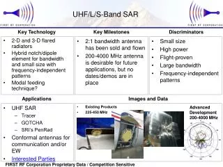
RF Attenuation in Different Wall Materials • N.C. Currie, D.D. Ferris, and al, “New law enforcement application of millimeter wave radar”, SPIE Vol. 3066, pp2-10, 1997
Propagation Modeling • Frequency domain measurement • VNA for insertion transfer function. Advanced Design System (ADS) models
UWB Antenna Consideration • Wide band-width • Good impedance match • Minimum waveform ringing • Minimum pulse dispersion • Small size • Low cost
TypesofUWB Antennas • Tapered slot:Two dimensional microstrip • TEM horn: Most commonly used • Bow-tie:Relatively high input impedance Requires a matching balun • Resister loaded dipole Low gain and low efficiency • Discone:High performance, Difficult to manufacture 3-D structure • Bicone:High performance, Difficult to manufacture 3-D structure • Log-periodic: Dispersive • Spiral: Dispersive
Antipodal Vivaldi Antenna • Developed by Gibson in 1979 • Wide band performance • Fabricated on dielectric substrates • Great potential to low cost and weight • Small size Tapered flares on different layers Dimension:2.15cm x 5.52cm Substrate:Roger 4003C, 10 mil-thick
Vivaldi Sub-array • 16 Element sub-array • Dim: 18 cm x 40 cm • Wilkinson power divider • Element spacing: 2.15 cm 7.5 GHz – 12.5 GHz
Pattern: Simulation Versus Measurement @ 10 GHz Measurement:13dB Gain, 4° Beamwidth Simulation: 15dB Gain, 3° Beamwidth
Measured Radiation Pattern E Plane H Plane
Transmitter/Receiver Structure 1 2 3 4 16 ........ Switch
UWB_SubHarmonic_Mixer • Why SubHarmonic_Mixer? • 1. Easy to implement in a PCB technology using coplanar lines. • 2. LO frequency can be lowered • 3. Provides very high isolation between the RF port , LO port and IF port. Specially the RF and LO have more than 40 dB isolation in the 8-12 GHz frequency range.
Harmonic Mixer Frequency Range, RF: 8 - 12GHz Frequency Range, LO: 8 - 12GHz Frequency Range, IF: 0.1- 2.5GHz Conversion loss <13dB RF to LO isolation > 45dB RF to IF isolation > 45dB LO to IF isolation > 45dB IP3 (Input) 14dBm LO input power : 7dBm
Parallel-Feedback Dielectric-Resonator Oscillator • Why DRO? • DROs are attractive microwave sources because of their high Q, low phase noise, good output power and their high stability versus temperature. • They represent a good compromise of costs, size, and performance compared to alternative signal sources such as cavity oscillators, microstrip oscillators or multiplied crystal oscillators. • The parallel-feedback with BJT DRO can achieve the highest performance in some frequency range.
DRO Oscillator Operating Frequency Range: 9.9-10.1GHz Phase noise: -95dBc @ 10KHz -120dBc @ 1 MHz Output power: 7 dBm Harmonics: -40 dBc min Spurious: - 80 dBc min Temperature stability: +/- 1MHz
Narrow Band Low Noise Amplifier Freq range: 9.9-10.1 GHz Gain: >11.5 dB Gain Flatness: +/- 0.5 dB Noise figure: 1.2 dB P1dB: 16 dBm IP3out: 24 dBm
UWB Power Amplifier Freq range: 2-18 GHz Gain: >12 dB Gain Flatness: +/- 0.5 dB Psat: 26 dBm P1dB: 25 dBm IP3out: 27 dBm
SP16T Using SPDT in Series Hittite SPDT (SMT) DC - 14.0 GHz
SP4T Measurements Frequency Range: 7 to 13 GHz IL: - 4dB with flatness: +/-1dB Isolation : <- 40dB
Test Fixture Design Top Side Bottom Side
RF Layout Frequency Range: 9 to 13 GHz IL: - 8dB with flatness: +/-2dB Isolation : <-45dB Switching Time: < 50ns
Pulse Width: Adjustable 400ps - 1ns Rise Time: 50ps Fall Time: 50ps Bandwidth: up to 2GHz
Solutions for DAQ System UWB Sampler: for hand-held portable model Oscilloscope: for experimental system PCI Digitizer: for ground vehicle based system ADC Chip: for hand-held portable model
Targets Location 20cm X 24cm 12cm X 24cm
Top View -- Hallway Geometry and UWB Radar Setup Concrete Wall 9.30m Radar Position Side Wall 2.85m Door 1 Door 2 1.02m Targets Metal-covered Door
Non-through-Wall Image Side Wall Door 2 Gas Tank Door 1 Cylindrical Target