Download
1 / 30
310 likes | 432 Vues
This work presents the development of advanced Ultra-Wideband (UWB) pulse-based test beds for communication and radar applications, focusing on innovative designs for human tissue-penetrating radio links and synchronized PPM modulation systems. The research includes applications for cochlear implants, exploring receiver architectures and power consumption efficiencies. Key results highlight performance metrics such as data rates and receiver sensitivities across different prototypes. The insights gained aim to contribute to the future of bio-communication technologies and UWB radar innovations.

E N D
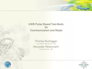
UWB Pulse Based Test-Beds for Communication and Radar Thomas Buchegger Linz Center of Mechatronics - ICIE Alexander Reisenzahn University of Linz – IME
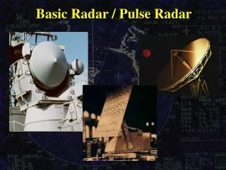
Outline • UWB Communication Test-Beds • Human Tissue PenetratingRadio Link Prototype • Cochlear Implant Application • PPM Test-Bed with Synchronization • Phase Modulated Transmitted Reference Systems • UWB Radar 2
Human Tissue PenetratingRadio Link Prototype • Modulation: On-Off Keying • PRF: 40 MHz • Data rate: 1.2 Mbps • Range: 1 m • Receiver: non-coherent detector • Power consumption (Rx): 20 mW Rx with Backward Diode: 0 mW UWB transmitter UWB detector receiver 4
Human Tissue PenetratingRadio Link Prototype – The Chochlear Implant Application outside componts of a chochlea implant UWB transmit signal • high power consumption • optical unfavorable 5
transmitter channel receiver LNA OPA UWB transmitter radio channel LP ADC PD oscilloscop PD micro controller external clock (Information) local oscillator UWB reference pulse DDS UWB PPM Test-Bed with Synchronization • block schematic of the prototype 6
UWB PPM Test-Bed with Synchronization Results: UWB PPM transmitter step recovery diodes data rate of 10Mbps UWB PPM coherent receiver correlation Receiver DDS for synchronization Synchronization algorithm: clock synchronization < 100 ppm data synchronization < 5 ms UWB PPM and OOK test bed 7
PMTR UWB Systems • Fast and easy synchronization with an integrating controller • Only one broadband mixer in the receiver • One pulse per bit 9
Simulation – DHTR, PMTR, EPMTR Systems DHTR in CM1 with 10 Mbps Comparison in AWGN channel PMTR in CM1 with 10 Mbps 11
PMTR - Hardware – Test-Bed Pulse generator of an UWB PMTR system PMTR transmitter Transmit pulses of a PMTR system 12
UWB-Radar Test-Bed Principle Radar test-bed block diagram 14
Transmitter – Pulse generation with D-Latch and single bipolar transistor • TTL-outputsignal drives transistor into saturation • Due to the step recovery effect a steep rising edge at the collector is generated • Differentiation with a short circuited stub • Elimination of the negative components with a clipping diode Pulse generation circuitry 15
Transmitter – Pulse generation with D-Latch and single bipolar transistor Output pulse Spectrum of the output pulse combined with the FCC indoor radiation mask 16
Receiver - Sampling Phase Detector • Step recovery diode generates step functions • Capacitors differentiate the steps to pulses and act as a filter for low frequencies • Schottky diodes are turned on by the pulses 18
Receiver – Down Conversion Pulse original Pulse downconverted 19
Measurements Conversion gain 1-dB compression point 20
Measurements • 1 dB-Compression Dynamic Range: > 42 dB • Receiver Sensitivity: -43 dBm Propagation delay 21
UWB Radar Test-Bed • No biasing • Low cost off the shelf components • FR4 PCB-material • Single 5 V power supply • Data transfer with USB-interface Radar test-bed 22
Receiver – Downconverter with SPD Down converter circuitry with SPD 24
Receiver – Downconverter Bandwidth • Bandwith is depending on the sampling pulse duration: • Pulse duration approximately the transit time of the SRD 25
Transmitter - Pulse Generation • D-Latch combined with step recovery diodes (SRD) • D-Latch combined with a single bipolar transistor 26
+5V L1 C1 C2 C3 D2 in D1 out GND I1 I2 Transmitter - D-Latch with SRD • Both SRDs biased in forward direction • D1 used for steepening the rising edge • D2 used for steepening the falling edge • Capacitors for DC-decoupling 27
Transmitter - D-Latch with SRD TTL Pulse UWB Pulse Input- and Output-Pulse Prototype 28
UWB PPM Test-Bed with Synchronization pulse repetition time Rx Signal necessary new pulse repetition time for a pulse shift of tPOS is used within the time tMC. Template Signal example: tPOS = 38 ps fPRF = 10 MHz f = 507 Hz tMC = 750 ns 29


![EFFECTIVE COMMUNICATION [UWB 10202]](https://cdn1.slideserve.com/3388499/effective-communication-uwb-10202-dt.jpg)


![EFFECTIVE COMMUNICATION [UWB 10202]](https://cdn3.slideserve.com/7063680/effective-communication-uwb-10202-dt.jpg)
![EFFECTIVE COMMUNICATION [UWB 10202]](https://cdn3.slideserve.com/7063827/effective-communication-uwb-10202-dt.jpg)