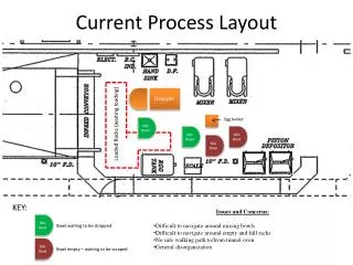
Process Layout
Process Layout. Chapter 7 July 20, 2005. Objectives of Facility Layout. Minimize material handling costs Utilize space efficiently Utilize labor efficiently Eliminate bottlenecks

Process Layout
E N D
Presentation Transcript
Process Layout Chapter 7 July 20, 2005
Objectives of Facility Layout • Minimize material handling costs • Utilize space efficiently • Utilize labor efficiently • Eliminate bottlenecks • Facilitate communication and interaction between workers, between workers and their supervisors, or between workers and customers • Reduce manufacturing cycle time or customer service time • Eliminate waste or redundant movement • Facilitate the entry, exit, and placement of material, products, or people • Incorporate safety and security measures • Promote product and service quality • Encourage proper maintenance activities • Provide a visual control of operations or activities • Provide flexibility to adapt to changing conditions
Grinding Forging Lathes Station 1 Station 2 Station 3 Station 4 Painting Welding Drills Milling Office Foundry machines Layout Types (a) Layout of a job shop (b) Layout of a production line Figure 7.3
Hybrid Layout • Cellular layouts • Group machines into machining cells • Flexible manufacturing systems • Automated machining & material handling systems • Mixed-model assembly lines • Produce variety of models on one line
Machine 2 Machine 3 Machine 1 Materials in Finished goods out Machine 4 Machine 5 Hybrid Layout: Group Technology One Worker, Multiple Machines Figure 7.4
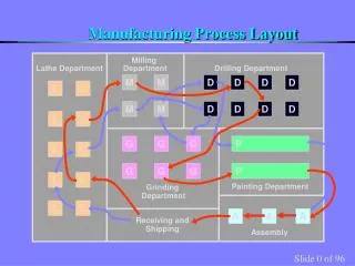
Lathing Milling Drilling D D L L M M D D L L M M Grinding L L M M G G Assembly L L G G A A Receiving and shipping A A G G Group Technology (a) Jumbled flows in a job shop without GT cells Figure 7.5
M L L G Assembly area D A A Cell 2 Cell 1 L M Receiving G G Cell 3 M L D Shipping Group Technology (b) Line flows in a job shop with three GT cells Figure 7.5
Cellular Layout HM VM • Identify families of parts with similar flow paths • Group machines into cells based on part families • Arrange cells so material movement is minimized • Locate large shared machines at point of use Worker 3 VM L Worker 2 G L Final inspection Finished part S Worker 1 Out In
Advantages/Disadvantages of Cellular Layout Disadvantages • Inadequate part families • Poorly balanced cells • Expanded training and scheduling of workers • Increased capital investment Advantages • Reduced material handling and transit time • Reduced setup time • Reduced work-in-process inventory • Better use of human resources • Easier to control • Easier to automate
Designing Flexible-Flow Layout • Gather Information • Space requirement • Available space • Closeness factors • Other considerations • Develop block plan • distance measure • Calculating a weighted-distance score • Design a detailed layout
Block Diagram [Problem 5-5] The design committee of a hospital has collected data on patient movement from similar facilities in hopes of making the new facility more efficient and customer-friendly. Improve the layout using weighted-distance score Initial Layout
Designing Line-Flow Layouts Line Balancing: the assignment of work to stations in a line so as to achieve the desired output rate with smallest number of workstations 2 constraints in line balancing: 1. Precedence requirements • Physical restriction, order of operations 2. Cycle time restrictions • Max. operating time allowed for each workstation • Depend on demand rate, production time
Station 1 Station 2 Station 3 Minutes per Unit 6 7 3 Assembly Line Balancing Concept Question: Suppose you load work into the three work stations below such that each will take the corresponding number of minutes as shown. What is the cycle time of this line? Answer: The cycle time of the line is always determined by the work station taking the longest time. In this problem, the cycle time of the line is 7 minutes. There is also going to be idle time at the other two work stations.
Line Balancing Process 1. Draw and label a precedence diagram. 2. Calculate the desired cycle time required for the line. 3. Calculate the theoretical minimum number of workstations. 4. Group elements into workstations, recognizing cycle time and precedence constraints. 5. Calculate the efficiency of the line. 6. Stop if theoretical minimum number of workstations on an acceptable efficiency level reached. If not, go back to step 4.
Ex: Line Balancing(also see Example 7.3) A company must produce 600 unit output in a 40-hour week. Given the following conditions, balance the assembly line
Ex: Line BalancingAdditional Example The work elements, precedence requirements and time requirements to assemble a picture frame are shown here. • Construct a precedence diagram of the process and label task times. • Set up an assembly line capable of producing 1,600 frames per 40-hour week. • Calculate the efficiency and balance delay of the line. • Calculate the maximum number of frames that can be assembled each week. • Rebalance the line for maximum production. Indicate the composition of each station. • Assume the company can sell as many frames as can be produced. If workers are paid $8 an hour and the profit per frame is $5, should the production quota be set to the maximum? Assume one worker per station.