A Decomposition Algorithm to Structure Arithmetic Circuits
Learn about the algorithmic approach for optimizing arithmetic circuits through progressive decomposition to achieve faster and smaller designs. Discover strategies, experimental results, and comparison with traditional methods.

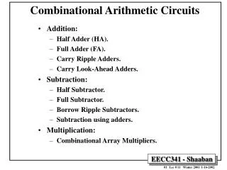
A Decomposition Algorithm to Structure Arithmetic Circuits
E N D
Presentation Transcript
A Decomposition Algorithm to Structure Arithmetic Circuits Ajay K. Verma, Philip Brisk, Paolo Ienne Ecole Polytechnique Fédérale de Lausanne (EPFL) International Workshop on Logic and Synthesis August 1, 2009
Logic synthesis tools Local optimization via Boolean minimization Architectural transformation Not with “traditional” logic synthesis Ripple-Carry Adder Carry-Lookahead Adder Logic Optimization Strategies 1
xi = a15a14 … a15-(i-2)a15-(i-1)a15-i Naïve Leading Zero Detector xi is TRUE if (i+1)th most-significant bit is the leading non-zero bit Convert xi to a binary number 2
Comparison 0.36 ns (427 μm2) 0.30 ns (392 μm2) 16% faster, 8% smaller 4
Algorithmic Overview Progressive Decomposition Algorithm… … and its shortcomings [Verma et al., DAC 2007] New Algorithm Experimental Results Conclusion Outline 5
Leader Expressions Sufficient to evaluate expression Once evaluated, you can discard input bits Works for circuits with “effective online algorithms” Input Condensation IN IN Leader Expressions One Big Circuit L |L| < |IN| Smaller Circuit Recursively compute leader expressions again OUT OUT 6
8:4 Parallel Counter s c (Leader Expressions) 7
Hierarchical Circuit Construction Use leader expressions as building blocks to impose hierarchy 8
x y z z = f(x, y) Progressive Decomposition • Choose a subset of input bits • How many bits? • Many different combinations? • Find leader expressions • Optimize via Boolean ring properties • Find identities • Discard dependent expressions • Rewrite circuit in terms of leader expressions • Recursively process the remaining circuit 9
[Verma et al., DAC 2007] Entire algorithm based on Reed-Muller Form Rewrite ‘your’ optimizer, e.g., if you use AIGs or BDDs. Exponential blowup for leading one detector Cannot optimize multipliers Cannot optimize “structurable circuits” surrounded by peripheral logic Progressive Decomposition: Shortcomings and Concerns 10
E1 E2 19 19 M1 M2 M1 M2 E1 E2 sign 48 1 48 19 19 and 4 not s1 s2 sign xor 4 neg s1 s2 xor out out Compound Circuits g72x 12% faster, 55% larger 0.82 ns (7998 μm2) 0.94 ns (5142 μm2) 11
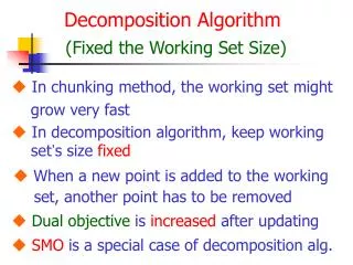
Progressive Decomposition Support sets are subsets of one another or disjoint Blocks must always reduce the number of inputs Support Sets 12
New Approach Support sets may overlap Relaxes input condensation constraint Both conditions are necessary to support multipliers Support Sets 13
Supports any representation with minimization algorithms We use BDDs Use SAT to check functional dependency [Lee et al., ICCAD 2007] Restrict Operator computes generalized cofactors [Coudert and Madre, ICCAD 1990] Entropy-based delay estimator [Macii et al., GLS-VLSI 1999] Imprecise, but effectively computes relative delays New Algorithm: Overview 14
Select every combination of k input bits for k < 6 Randomly assign values to the bits Estimate the complexity of the resulting circuit Input Bit Selection via Random Sampling a5 1 a3 a2 a1 0 b5 b4 b3 b2 1 1 a5 a4 a3 a2 0 1 b5 b4 1 1 b1 b0 Complexity of a 4-bit adder Complexity of a 6-bit adder 15
E – input expression B – chosen input bits S – leader expressions found thus far R – remaining bits R B S E Computing Leader Expressions Is E functionally dependent on SR? • Randomly sample R’s assignment space • Find missing leader expressions using SAT [Lee et al. ICCAD 2007] • Satisfying assignments provide missing leader expressions • S contains all leader expressions if no satisfying assignments exist 16
Leader expression is an input bit Non-disjunctive decomposition is required Remove from the set Leader expression contains no useful information Remove from the set a0b1 + a1b0 B = {a0, b0} a1 = b1 = 1 a0 + b0 Cannot help to compute the original expression Redundant Leader Expressions 17
Redundant Leader Expressions • Generalized cofactors • E = (a+b)x + (ab + c)y • g = a + b + c • E |g=0 = 0 • E |g=1 = (a + b)x + (ab + c)y = E • The general case is a reduction to SAT • Problem instances tend to be small 18
Rewrite as Shannon expansion using the Restrict operator Generalized cofactors are not unique The order in which the cofactors of each leader expression are computed may affect the result F |g=0 F F |g=1 g Rewrite Original Expression F = g(F |g=1) + g’(F |g=0) • For each cofactor: • Estimate the delay • Estimate delay of F based on Shannon expansion • Select the cofactor that leads to the minimal estimated delay of F D(F) max{D(F |g=1), D(F |g=0), D(g)} + D(mux) 19
Rinse, Repeat The leader expressions are now frozen, and the block that computes them is optimized. Optimize the remaining circuit We picked this set of input bits to optimize! We generated a set of leader expressions Local optimization using your favorite LS tool can’t hurt. 20
Experimental Setup Circuit written by hand Prog. Decomp. New Algorithm Known Arithmetic Circuits 1 2 3 4 Synopsis Design Compiler - compile_ultra - minimize delay Artisan Standard Cells UMC (90 nm) 21
Critical Path Delay Optimized for Area, Not Delay Progressive Decomposition Fails ns Original Progressive Decomposition Our Algorithm Library/Manual Implementation 22
Area Optimized for Area, Not Delay Progressive Decomposition Fails μm2 Original Progressive Decomposition Our Algorithm Library/Manual Implementation 23
Technique to structure arithmetic circuits Fixes shortcomings of Progressive Decomposition Our approach is orthogonal to classical Boolean minimization techniques Discovered new implementation of a k-input MAX function Similar structure to LZD Circuit Will appear at ICCAD 2009 Conclusion 24
Computing Leader Expressions Two different input assignments Original Variables B = {b1, …, bm} R = {r1, …, rn} Dummy Variables C = {c1, …, cm} S = {s1, …, sn} R B Extra Constraints [Lee et al., ICCAD 2007] ri = si, 1 < i < n For each leader expression ej: ej(b1, …, bm) = ej(c1, …, cm) E(b1, …, bm, r1, …, rn) E(c1, …, cm, s1, …, sn) S ej E
B = {x, y, z} X E E’ Input Bit Selection Compute every combination of k input bits for k < 6 B = {x, y, z} E’ |xyz=000 E’ |xyz=001 … E’ |xyz=111 Use delay estimator for each E’ The complexity of E’ is the metric by which we evaluate each group of input bits Assign values to x, y, z using random sampling