Arithmetic Circuits
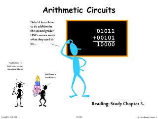
Arithmetic Circuits. Didn’t I learn how to do addition in the second grade? UNC courses aren’t what they used to be. 01011 +00101 10000. Finally; time to build some serious functional blocks. We’ll need a lot of boxes. Reading: Study Chapter 3. Review: 2’s Complement. N bits. -2 N-1.

Arithmetic Circuits
E N D
Presentation Transcript
Arithmetic Circuits Didn’t I learn how to do addition in the second grade? UNC courses aren’t what they used to be... 01011+0010110000 Finally; time to build some serious functional blocks We’ll need a lot of boxes Reading: Study Chapter 3.
Review: 2’s Complement N bits -2N-1 2N-2 … … … 23 22 21 20 Range: – 2N-1 to 2N-1 – 1 “sign bit” “binary” point 8-bit 2’s complement example: 11010110 = –27 + 26 + 24 + 22 + 21 = – 128 + 64 + 16 + 4 + 2 = – 42 If we use a two’s-complement representation for signed integers, the same binary addition procedure will work for adding both signed and unsigned numbers. By moving the implicit “binary” point, we can represent fractions too: 1101.0110 = –23 + 22 + 20 + 2-2 + 2-3 = – 8 + 4 + 1 + 0.25 + 0.125 = – 2.625
A B CO CI S A B CO CI S A B CO CI S A B CO CI S A B CO CI S FA FA FA FA FA Carries fromprevious column 1 1 0 1 Adding two N-bit numbers produces an (N+1)-bit result Let’s start by building a block that adds one column: Then we can cascade them to add two numbers of any size… A3 B3 A2 B2 A1 B1 A0 B0 S4 S3 S0 S1 S0 Binary Addition Here’s an example of binary addition as one might do it by “hand”: A: 1101B:+ 010110010
Designing a Full Adder: From Last Time • Start with a truth table: • Write down eqns for the“1” outputsCo = CiAB + CiAB + CiAB + CiABS = CiAB + CiAB + CiAB + CiAB • Simplifing a bitCo = Ci(A + B) + ABS = Ci A B Co = Ci(A B) + AB S = Ci (A B)
A B “Carry” Logic CI CO “Sum” Logic S For Those Who Prefer Logic Diagrams … • A little tricky, but only 5 gates/bit Co = Ci(A B) + AB S = Ci (A B)
A B CO CI S A B CO CI S A B CO CI S A B CO CI S FA FA FA FA ~ = bit-wise complement B 0 B 1 B B So let’s build an arithmetic unit that does both addition and subtraction. Operation selected by control input: B3 B2 B1 B0 Subtract But what about the “+1”? A3 A2 A1 A0 S4 S3 S0 S1 S0 Subtraction: A-B = A + (-B) Using 2’s complement representation: –B = ~B + 1
-or- Condition Codes Besides the sum, one often wants four other bits of information from an arithmetic unit: To compare A and B, perform A–B and use condition codes: Signed comparison: LT NV LE Z+(NV) EQ Z NE ~Z GE ~(NV) GT ~(Z+(NV)) Unsigned comparison: LTU C LEU C+Z GEU ~C GTU ~(C+Z) • Z (zero): result is = 0 big NOR gate • N (negative): result is < 0 SN-1 • C (carry): indicates that add in the most significant position produced a carry, e.g., • “1 + (-1)” from last FA • V (overflow): indicates that the answer has too many bits to be represented correctly by the result width, e.g., “(2i-1 - 1)+ (2i-1- 1)”
A B CO CI S A B CO CI S A B CO CI S A B CO CI S A B CO CI S FA FA FA FA FA A B CI CO S TPD of Ripple-Carry Adder An-1 Bn-1 An-2 Bn-2 A2 B2 A1 B1 A0 B0 C … Sn-1 Sn-2 S2 S1 S0 Worse-case path: carry propagation from LSB to MSB, e.g., when adding 11…111 to 00…001. tPD = (tPD,XOR +tPD,AND + tPD,OR) +(N-2)*(tPD,OR + tPD,AND) + tPD,XOR (N) A,B to CO CI to CO CIN-1 to SN-1 (N) is read “order N” and tells us that the latency of our adder grows in proportion to the number of bits in the operands.
A B CI CO To generate the Carry of the Nth bit: S CN = GN-1 + PN-1CN-1 = GN-1 + PN-1 GN-2 + PN-1 PN-2CN-2 = GN-1 + PN-1 GN-2 + PN-1 PN-2GN-3 + … + PN-1 ...P0CIN CN in only 3 (!) gate delays: 1 for P/G generation, 1 for ANDs, 1 for final OR G P Faster Carry Logic Let’s see if we can improve the speed by rewriting the equations for COUT: Actually, P is usually defined as P = ABwhich won’t changeCOUT but will allow usto express S as asimple function ofP and CIN: S = P CIN COUT = AB + ACIN + BCIN = AB + (A + B)CIN = G + P CIN where G = AB and P = A + B generate propagate
N-Bit Addition in Constant Time? • So if we had (N+1)-input gates and didn’t mind a lot of loading on the P signals, the propagation delay of adder built using P/G equation to compute CIN of each bit would be: • 4 gate delays (1) • Of course, this is impractical when N is “large” (i.e. > 4) but it does lead to some interesting ideas: • w faster ripple-carry implementations • w hierarchical carry-lookahead adders
A B CO C I G P S A B CO C I G P S FA FA GH PH GH PH GL PL GL PL GP GP GHL PHL GHL PHL Carry-Lookahead Adders (CLA) We can build a hierarchical carry chain by generalizing our definition of the Carry Generate/Propagate (GP) Logic. We start by dividing our addend into two parts, a higher part, H, and a lower part, L. The GP function can be expressed as follows: Generate a carry out if the high part generates one, or if the low part generates one and the high part propagates it. Propagate a carry if both the high and low parts propagate theirs. GHL = GH + PH GL PHL = PH PL P/G generation 1st level of lookahead Hierarchical building block
A BCO CI G P S A BCO CI G P S A BCO CI G P S A BCO CI G P S A BCO CI G P S A BCO CI G P S A BCO CI G P S A BCO CI G P S FA FA FA FA FA FA FA FA GH PH GL GH PH GL GH PH GL GH PH GL GH PH GL GH PH GL GH PH GL GP GP GP GP GP GP GP GHL PHL PL GHL PHL PL GHL PHL PL GHL PHL PL GHL PHL PL GHL PHL PL GHL PHL PL 8-bit CLA (GP Generation) A7 B7 A6 B6 A5 B5 A4 B4 A3 B3 A2 B2 A1 B1 A0 B0 G7-6 P7-6 G5-4 P5-4 G3-2 P3-2 G1-0 P1-0 Log2(N) G7-4 P7-4 G3-0 P3-0 G7-0 P7-0 We can build a tree of GP units to compute the generate and propagate logic for any sized adder. For a 2N-bit adder, we need 2N-1 GP units. C = G7 + P7 G6 + P7 P6G5 + P7 P6P5G4 + … + P7 ...P0CIN P7-0 G7-0
8-bit CLA (Carry Generation) Now, given a the value of the carry-in of the least-significant bit,we can generate the carries for every adder. cj = Gj-i + Pj-ici C7 C6 C5 C4 C3 C2 C1 C0 cj cj cj cj G6 P6 G4 P4 G2 P2 G0 P0 Gj-i Gj-i Gj-i Gj-i C C ci ci ci ci C C Pj-i Pj-i Pj-i Pj-i ci ci ci ci C6 C4 C2 C0 cj cj G5-4 P5-4 G1-0 P1-0 Gj-i Gj-i Log2(N) ci ci C C Pj-i Pj-i ci ci Notice that the inputs on the right of each C blocks are the same as the inputs on the left of each corresponding GP block. C4 C0 G3-0 P3-0 cj Gj-i ci C Pj-i ci C0
A BCO CI G P S A BCO CI G P S A BCO CI G P S A BCO CI G P S A BCO CI G P S A BCO CI G P S A BCO CI G P S A BCO CI G P S FA FA FA FA FA FA FA FA A B CI tPD = (log(N)) CO GH PH S GL PL GP Notice that we don’t need the carry-out output of the adder any more. GHL PHL GH PH Cj GH PH Cj GH PH Cj GL PL Ci GL PL Ci GL PL Ci GP/C GP/C GP/C GH PH Cj cj GHL PHL Ci GHL PHL Ci GHL PHL Ci + GL = GL PL CI C ci GP/C PL ci GHL PHL Ci G P 8-Bit CLA (Complete) A7 B7 A6 B6 A5 B5 A4 B4 A3 B3 A2 B2 A1 B1 A0 B0 GH PH Cj GH PH Cj GH PH Cj GH PH Cj GL PL Ci GL PL Ci GL PL Ci GL PL Ci GP/C GP/C GP/C GP/C GHL PHL Ci GHL PHL Ci GHL PHL Ci GHL PHL Ci C0
Carry-Skip Adders Idea: full P/G equations are complicated, but P by itself is simple. So just use P to “skip” carry across a block of ripple-carry adders: A C K-bit blocks (K=4 in figure) B • Carries ripple simultaneously through each block; if block generates a carry, it appears on carry-out of block (similar to G). If carry-in is 0 at start of operation, no spurious carry-outs will be generated. • If carry-in and PBLOCK are both true, carry skips to next block • Carry ripples though final block. tPD = 2*[K+ (N/K – 2) + K]With variable size blocks tPD (sqrt(N))
Carry-Select Adders Idea: do two additions, one assuming carry-in is 0, the other assuming carry-in is 1. Use MUX to select correct answer when correct carry-in is known. Left blocks can be bigger – more ripple time time while waiting for select With one stage: 50% more cost, but twice as fast as ripple-carryWith multiple (variable-size) blocks: tPD (sqrt(N))
A A B B Add Add/Sub S S Adder Summary • Adding is not only a common, but it is also tends to be one of the most time-critical of operations. As a result, a wide range of adder architectures have been developed that allow a designer to tradeoff complexity (in terms of the number of gates) for performance. Smaller / Slower Bigger / Faster RippleCarry Carry Skip Carry Select Carry Lookahead A this point we’ll define a high-level functional unit for an adder, and specify the details of the implementation as necessary. sub
X7 X6 X5 X4 X3 X2 X1 X0 R7 R6 R5 R4 R3 R2 R1 R0 0 1 0 1 0 1 0 1 0 1 0 1 0 1 0 1 “0” SHL1 Shifting Logic • Shifting is a common operation that is applied to groups of bits. Shifting can be used for alignment, as well as for arithmetic operations. • X << 1 is approx the same as 2*X • X >> 1 can be the same as X/2 • For example: • X = 2010 = 000101002 Left Shift: (X << 1) = 001010002 = 4010 Right Shift: (X >> 1) = 000010102 = 1010 Signed or “Arithmetic” Right Shift: (-X >> 1) = (111011002 >> 1) = 111101102 = -1010
X7 X6 X5 X4 X3 X2 X1 X0 X7 X6 X5 X4 X3 X2 X1 X0 X7 X6 X5 X4 X3 X2 X1 X0 S7 S6 S5 S4 S3 S2 S1 S0 R7 R6 R5 R4 R3 R2 R1 R0 S7 S6 S5 S4 S3 S2 S1 S0 0 1 0 1 0 1 0 1 0 1 0 1 0 1 0 1 0 1 0 1 0 1 0 1 0 1 0 1 0 1 0 1 0 1 0 1 0 1 0 1 0 1 0 1 0 1 0 1 “0” “0” “0” SHL2 SHL1 SHL3 More Shifting Using the same basic idea we can build left shifters of arbitrary sizes using muxes. Each shift amount requires its own set of muxes. Hum, maybe we could do something more clever.
T7 T6 T5 T4 T3 T2 T1 T0 0 1 0 1 0 1 0 1 0 1 0 1 0 1 0 1 0 1 0 1 0 1 0 1 0 1 0 1 0 1 0 1 0 1 0 1 0 1 0 1 0 1 0 1 0 1 0 1 And, if we add one more “shift-left-4” shifter we can do any shift up to 7 bits! So, let’s put a box around it and call it a new functional block. A N-bits Left Barrel Shifter log2(N) bits S “0” SHL4 N-bits Y Barrel Shifting X7 X6 X5 X4 X3 X2 X1 X0 R7 R6 R5 R4 R3 R2 R1 R0 S7 S6 S5 S4 S3 S2 S1 S0 If we connect our “shift-left-two” shifter to the output of our “shift-left-one” we can shift by 0, 1, 2, or 3 bits. “0” “0” SHL1 SHL2
A0 A7 A1 A6 A2 A5 A3 A4 A4 A3 A5 A2 A6 A1 A7 A0 1 0 1 0 1 0 1 0 1 0 1 0 1 0 1 0 RGT Y0 Y7 Y1 Y6 Y2 Y5 Y3 Y4 Y4 Y3 Y5 Y2 Y6 Y1 Y7 Y0 1 0 1 0 1 0 1 0 1 0 1 0 1 0 1 0 RGT Z7Z6 Z5 Z4 Z3 Z2 Z1 Z0 Barrel Shifting with a Twist • At this point it would be straightforward to construct a “Right barrel shifter” unit. However, a simple trick that enables a left shifter to do both. A7-0 Left Barrel Shifter SHFT Y7-0
Boolean Operations • It will also be useful to perform logical operations on groups of bits. Which ones? ANDing is useful for “masking” off groups of bits. ex. 10101110 & 00001111 = 00001110 (mask selects last 4 bits) ANDing is also useful for “clearing” groups of bits. ex. 10101110 & 00001111 = 00001110 (0’s clear first 4 bits) ORing is useful for “setting” groups of bits. ex. 10101110 | 00001111 = 10101111 (1’s set last 4 bits) XORing is useful for “complementing” groups of bits. ex. 10101110 ^ 00001111 = 10100001 (1’s complement last 4 bits) NORing is useful.. Uhm, because John Hennessy says it is! ex. 10101110 # 00001111 = 01010000 (0’s complement, 1’s clear)
Bi Ai This logic block is repeated for each bit (i.e. 32 times) 00 01 10 11 Bool Qi Boolean Unit (The book’s way) • It is simple to build up a Boolean unit using primitive gates and a mux to select the function. • Since there is no interconnectionbetween bits, this unit canbe simply replicated at eachposition. The cost is about7 gates per bit. One for each primitive function,and approx 3 for the 4-input mux. • This is a straightforward, but not too elegant of a design.
I should pay more attention to those muxes OR XOR OR XOR AND OR NOR 00 01 10 11 Ai , Bi A B Boolean bool Qi Q Cooler Bools • We can better leverage a mux’s capabilities in our Boolean unit design, by connecting the bits to the select lines. • Why is this better? • While it might take a littlelogic to decode the truthtable inputs, you only haveto do it once, independentof the number of bits. • It is trivial to extend thismodule to support any 2-bitlogical function. (How about NAND, John? Actually A & /B might be more useful) Which ever way makes the most sense to you. Let’s get a box around it!
A B Sub Boolean Bidirectional Barrel Shifter Add/Sub Bool Shft 1 0 Math 1 0 R … An ALU, at Last • Now we’re ready for a big one! An Arithmetic Logic Unit. That’s a lot of stuff FlagsV,C N Flag Z Flag