Arithmetic Circuits and Control Units in Digital Systems
Explore the operation of serial adders, parallel multipliers, and dividers in digital circuits, along with the control signals that regulate arithmetic functions. Learn about shift registers, control unit realization, and multiplication/division processes.

Arithmetic Circuits and Control Units in Digital Systems
E N D
Presentation Transcript
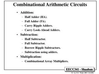
Lecture 16 Arithmetic Circuits • Serial adder • Parallel multiplier • Divider • Control circuit outputs a sequence of control signals that cause arithmetic operation to take place at appropriate times. Chap 18
Serial Adder • X register • Accumulator: X = X+Y • Y register • Addend register: cyclic shift register • after shifting 4 times, it is back in its original state • Sh: shift signal • SI: serial input Chap 18
Serial Adder • At the falling clock edge and Sh= 1 • Si (sum bi) is shifted into x • Carry bit is stored in the D FF. • Register y is rotated one bit to the right. • Initial loading circuit not shown. Sh Carry is only updated when shift occurs. Chap 18
Serial Adder s0, c1 ready • At the falling clock edge and Sh= 1 Before the first shift Chap 18
Control Unit Realization • A start signal: St. • If St is asserted, then the control unit puts out 4 shift signals then stops. St= Chap 18
Serial Processing Unit • A start signal: St. • If St is asserted, then the control unit puts out n shift (Fig. a) St = 1 for only one clock time. • If St remains 1 until the shifting is completed, then a stop state is required. (Fig. b) Chap 18
Multiplier • Add shift add shift add…. • Check the right most bit of the multiplier. 1=> add + shift, 0=> shift. Shift right Add Chap 18
Multiplier Diagram • Product register [3:0] = multiplier • Load: ACC = 00000::multiplier • Sh: shift ACC 1 bit right. • St: start signal, start operation. • M bit: M= 1, add + shift. M = 0, shift. Chap 18
Multiplier Control • M/Ad: If M = 1 then Ad = 1, the rest of outputs is 0. • How many clocks are required for a multiplication? Reset (waits for start) One bit Chap 18
Multiplier Control • Multiplication for a large number of bits • User a counter. When n-1 shifts have occurred, K = 1.Then go to S3 for completion (last shift also). Chap 18
Division • Division = subtraction and shift • 8-bit dividend by a 4-bit divisor to get a 4-bit quotient • Use a 9-bit dividend register for shifting the dividend left. • Store quotient bit by bit into the dividend register when shifting left. Chap 18
Binary Division • Use a 9-bit dividend register for shifting the dividend left. • Store quotient bit by bit into the dividend register when shifting left. Chap 18
135 0 1 0 0 0 1 0 0 0 0 1 0 1 0 0 1 1 0 1 1 1 1 1 1 1 0 1 1 1 1 1 1 1 1 1 1 0 0 0 Binary Division • Use a 9-bit dividend register for shifting the dividend left. • Store quotient bit by bit into the dividend register when shifting left. Negative (no sub, shift) empty After the first Shift. Q3 First sub Chap 18
minus 0 0 0 0 0 0 0 1 1 1 1 0 1 1 1 0 1 1 0 1 1 1 1 1 1 0 1 1 0 1 0 1 1 0 0 0 Remain 0 bc. minus Then shift left 1 1 1 1 1 1 1 1 1 0 0 0 sub Q1 =1 bc. sub remainder quotient Binary Division (cont.) • Use a 9-bit dividend register for shifting the dividend left. Shift Not enough for sub. Chap 18
Binary Division (cont.) • In this example, if Q > 15, then overflow occurs. • If initially X8X7X6X5X4 >= Y3Y2Y1Y0, then the quotient will be greater than 15 and overflow occurs. • Shift signal: Sh • Shift the dividend one place to the left on the next rising clock edge. • Subtract signal:Su • Use a subtracter to compute X8X7X6X5X4 - Y3Y2Y1Y0 (this is combinational circuit). • Su loads the subtracter output into X8X7X6X5X4 and sets the quotient bit to 1 on the next rising edge. Chap 18
Binary Division (cont.) • Sh: shift the dividend register 1 bit left. • Su: load X8 to X4 for the result of subtraction, (Ld). Set X0 to 1. Chap 18
Binary Division (cont.) • C: if divisor > X8 to X4, C=0. No subtraction, generate shift. Sh=1. • Otherwise C =1, subtract signal is generated (Su =1), Q bit is set to 1. Chap 18
Binary Division (cont.) • St: start signal. St =1, load 8-bit dividend and 4-bit divisor into registers. If C = 1 at this moment, this is overflow. Set V flag. Chap 18
Binary Division (cont.) • St: start signal. St =1, load 8-bit dividend and 4-bit divisor into registers. If C = 1 at this moment, this is overflow. Set V flag. • Normally, C =0 at first. • After C=1 (do sub), then C will always be 0. S0 S1 S2 St Compare and sub, C=0, set Sh =1. St =1. Set Load =1 Final sub Chap 18
Binary Division (cont.) • One-hot assignment Chap 18
Binary Division (cont.) • Complete circuit Chap 18