XII. Site Specific Predictions Using Ray Methods
XII. Site Specific Predictions Using Ray Methods. General considerations Ray tracing using 2D building database Ray tracing from a 3D building database Slant plane / vertical plane method Full 3D method Vertical lane Launch (VPL) method Ray tracing for indoor predictions

XII. Site Specific Predictions Using Ray Methods
E N D
Presentation Transcript
XII. Site Specific Predictions Using Ray Methods • General considerations • Ray tracing using 2D building database • Ray tracing from a 3D building database • Slant plane / vertical plane method • Full 3D method • Vertical lane Launch (VPL) method • Ray tracing for indoor predictions • Using ray methods to predict statistics of delay and angle spread Polytechnic University, Brooklyn, NY
Goals and Motivation • Goal • Make propagation predictions based on the actual shape of the buildings in some region • Motivation • Achieve a desired quality of service in high traffic density areas • Install systems without adjustment • System simulations and studies • Predict higher order channel statistics Polytechnic University, Brooklyn, NY
Ray Techniques for Site Specific Predictions • Numerical solvers (finite difference, finite element and moment methods) not practical for urban dimension • Ray techniques are the only viable approach • Predictions using 2D building data base Pin/cushion vs. image method • Prediction using 3D building data base Vertical plane/slant plane - enhanced 2D methods Full 3D method Vertical plane launch - approximates full 3D method Polytechnic University, Brooklyn, NY
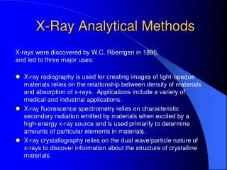
Physical Phenomena and Database Requirements • Physical phenomena that can be accounted for • Ground reflection and blockage • Specular reflection at building walls • Diffraction at building corners, roofs • Diffuse scattering from building walls (for last path segment) • Database requirements for predictions • Terrain • Buildings decomposed into groups of polyhedrons that are : Stacked (wedding cake buildings) or side-by-side Polygonal base with vertical sides Some codes assume flat roofs Vector vs pixel (area element) data base • Reflection coefficients at walls, diffuse scattering coefficient Polytechnic University, Brooklyn, NY
Specular vs Diffuse Reflection from Walls • Complex construction leads to scattering • Mixture of construction materials • Architectural details • Windows - glass, frame • Simplifying approximations for large distances r2 r1 q s1 s2 Specular reflection ~ 1/ (r1 + r2)2 Diffuse reflection ~ A/ (s1 s2) For all construction, | ( )| 1 for 90° Polytechnic University, Brooklyn, NY
Modeling Limitations • Cannot accurately predict phase of ray fields • Position accuracy of building data base ~ 0.5 m • Do not know wall construction - uncertainty in magnitude and phase of reflection coefficient • Local scattering contributions not computed • Do not consider vehicles, street lights, signs, people, etc. • Most codes do not include diffuse scattering • Cannot predict fast fading pattern in space • Predict small area average by summing ray powers • Can be used to predict statistical parameters Polytechnic University, Brooklyn, NY
Ray Tracing Using a 2D Building Database • Building are assumed to be infinitely high • Almost all models neglect transmission through the building • 2D ray tracing around building in the horizontal plane • Rays that are considered • Multiple specular reflections from the building walls • Single or double diffraction at the vertical edge of a building • Ground reflection • Diffuse scattering from the building walls • Advantages: • Account for low base station antennas among high rise buildings • Computationally efficient • Limitations: • Less accurate in an area of mixed building heights • Fails for rooftop base stations Polytechnic University, Brooklyn, NY
Rx Rx Rx Rx Tx No Diffraction Single Diffraction Double Diffraction Two Dimensional Ray Tracing Technique Rays are traced to corners, which act as a secondary sources for subsequent trace. Polytechnic University, Brooklyn, NY
Rx Rx Rx Tx Tx Image vs Pin Cushion Method for 2D Rays Image Method Pin Cushion Method Reflected ray paths found from multiple Rays traced outward from the source imaging of the source in the building walls at angular separation,Dq << w/R, must determine if the ray from an image must use capture circle to find rays passes through the actual wall, or through that illuminate the receiver (or the analytic extension of the wall. equivalent procedure). Dia =L Polytechnic University, Brooklyn, NY
Footprints of Buildings in the High-Rise Section of Rosslyn, Virginia Polytechnic University, Brooklyn, NY
Comparison of Measured and, 2D computed Path Gain for Low Base Station at TX4bf = 1900MHz Polytechnic University, Brooklyn, NY
Predictions for a Generic High Rise Environment • Rectangular Street Grid • Propagation Down Streets, Around Corners • - Specular Reflection at Building Walls Diffraction • at Building Corners Polytechnic University, Brooklyn, NY
High Rise Buildings in Upper Manhattan, NY Polytechnic University, Brooklyn, NY
y x Propagation Down the Urban Canyonsof High Rise Buildings Building Building Building A TX B MAIN STREET RX0 Building Building Building 4 2 1 3 Wy RX2 RX1 Building Building Building Ly Wy Lx Polytechnic University, Brooklyn, NY
Reflection and Diffraction Around Corners Building Building Building 3 1 2 TX Building Building Building RX Polytechnic University, Brooklyn, NY
Ray Path for High Rise Model • All Path Include Direct Path + Path from Image Source to Account for Ground Reflections • Main Street • Rm: m reflections at building on main street • Perpendicular Streets - one turn paths • Rmn: m reflections at building on main street, n reflections on perpendicular street + ground • RmDRn: building reflections separated by corner diffractions • Parallel Streets - two turn paths • Rmnp: m, n, p, building reflections on main, perpendicular, parallel street • RmDRnp, RmnDRp,: building reflections + diffraction at a single corner • RmDRn DRp: building reflections + diffraction at two corners Polytechnic University, Brooklyn, NY
Predictions in LOS and Perpendicular Streets LOS TX X X X X X Received Power (dB) Distance (m) Polytechnic University, Brooklyn, NY
Turning Corners in Manhattan Polytechnic University, Brooklyn, NY
Cell shape in a High Rise Environment Polytechnic University, Brooklyn, NY
Rx c b c d Tx Building Height d b Rx 0 Right propagation channel Range Left propagation channel Tx Vertical Plane/Slant Plane Method Rays are traced in the slant plane containing TX and RX to account for propagation around buildings. Rays are traced in the vertical plane containing TX and RX to account for propagation over buildings. Polytechnic University, Brooklyn, NY
Slant/Vertical Plane Predictionfor Aalborg, Denmark at 955MHzT. Kurner, D.J. Cichon and W. Wiesbeck, “Concepts and Results for 3D Digital Terrain-basedWave Propagation Models: An Overview,” IEEE Jnl. JASC 11, Sept. 1993 Polytechnic University, Brooklyn, NY
Missing Rays in Slant Approximation • Unless the building faces are perpendicular to the vertical • plane, reflected rays lie outside of the vertical plane • Multiply reflected rays will not lie in the slant plane • Neglects rays that go over and around building • Missing rays cause significant errors for high base station • antenna Polytechnic University, Brooklyn, NY
Transmitter and Receiver Locations forCore Rosslyn Propagation Predictions Polytechnic University, Brooklyn, NY
Slant/Vertical Plane Prediction for Rooftop Antenna at 900MHz Polytechnic University, Brooklyn, NY
Ray Tracing Using a 3D Building Database • Rays that are considered: • Can account for all rays in 3D space • Some programs consider diffuse scattering • Some simplification is made, i.e. flat roofs and/or vertical walls • Rays that are not considered: • Often unable to include rays that undergo more than one diffraction • Usually does not include transmission into the buildings • Advantages: • Very robust model, works for many building environments • Limitations: • Limited to a maximum of 2 diffractions (unable to account for multiple rooftop diffraction) • Computationally very inefficient Polytechnic University, Brooklyn, NY
3D Predictions of Path Gain for Elevated Base Station at TX6 and f=908MHz Polytechnic University, Brooklyn, NY
b b a a g Limitation of Regular 3D Ray Tracing MethodEach segment of each edge is a source of a cone of diffracted rays Polytechnic University, Brooklyn, NY
Vertical Plane Launch (VPL) Method • Finds rays in 3D that are multiply reflected and diffracted • by buildings • Assumes building walls are vertical to separate the trace • into horizontal and vertical components • Pin cushion method gives the ray paths in the horizontal • plane • Analytic methods give the ray paths in the vertical direction • Makes approximation: rays diffracted at a horizontal • edge lie in the vertical plane of the incident ray, or the • vertical plane of the reflected rays Polytechnic University, Brooklyn, NY
Vertical plane containing forward diffracted rays Vertical plane containing back diffracted rays Vertical plane containing reflected and back diffracted rays Cone of diffracted rays Physical Approximation of the VPL Method Treats rays diffracted at horizontal edges as being in the vertical planes defined by the incident or reflected rays (replaces diffraction cone by tangent planes) Polytechnic University, Brooklyn, NY
VPL Method for Approximate 3D Ray Tracing Polytechnic University, Brooklyn, NY
8 4 5 9 7 Diffraction Edge Reflection 10 6 3 1 2 Reflections and Rooftop Diffractions for VPL Method Form a Binary Tree Polytechnic University, Brooklyn, NY
Transmitter and Receiver Locations forCore Rosslyn Propagation Predictions Polytechnic University, Brooklyn, NY
Measurements and VPL Predictions forRooftop Antenna (TX6 and f=908MHz) Without diffuse: h = -0.75 dB s = 5.43 dB With diffuse: h = -0.74 dB s = 5.44 dB Polytechnic University, Brooklyn, NY
Measurements and VPL Predictions for Street Level Antenna (TX1a and f=908MHz) Without diffuse: h = -0.42 dB s = 8.92 dB With diffuse: h = 0.49 dB s = 8.34 dB Polytechnic University, Brooklyn, NY
Tx and RX Locations in Munich Polytechnic University, Brooklyn, NY
Measurements and VPL Predictions in MunichRoute 1, f=900MHz, = 0.40 dB, s = 8.67 dB Polytechnic University, Brooklyn, NY
Diffraction at Building Corners • Important to correctly model shape of building corners • Luebbers diffraction coefficient used by many to model diffraction at building corners • Heuristic coefficient for lossy dielectric wedges • Developed for forward diffraction over hills • Exhibits nulls in the back diffraction direction that are not physical • Building corners are not dielectric wedges, e.g., fitted with windows, metal framing • Need a single diffraction coefficient to use for all corners Polytechnic University, Brooklyn, NY
For low base station (BS) antenna, reflection from glass doors at Corner A influences received signal on street L-M. Reflection Away From Glancing Is Influenced by Wall Properties Polytechnic University, Brooklyn, NY
Measurements Along Street L-M Show Influence of Corner A on Ray Results Polytechnic University, Brooklyn, NY
Walls with windows Some Examples of Building Corner Construction and Diffracted Rays Polytechnic University, Brooklyn, NY
Comparison of Diffraction Coefficients (900 MHz) Polytechnic University, Brooklyn, NY
Comparison of Power Predictions With Helsinki Measurements at 2.25 GHz Polytechnic University, Brooklyn, NY
Comparison of DS Predictions With Helsinki Measurements at 2.25 GHz Polytechnic University, Brooklyn, NY
Summary of Prediction Errors on Different Routes in Helsinki for Low Antennas Polytechnic University, Brooklyn, NY
Conclusions • Site specific predictions are possible with accuracy Average error ~ 1 dB RMS error ~ 6 - 10 dB • Requires multiple interactions for accurate predictions Six or more reflections required for best accuracy Double diffraction at vertical edges is sometimes needed • Lubbers diffraction coefficient needs modification Polytechnic University, Brooklyn, NY
Ray Tracing Inside Buildings • Ray tracing over one floor • Propagation through the clear space between furnishings and ceiling structure • Propagation between floors Polytechnic University, Brooklyn, NY
2-D codes for Propagation Over One Floor • Transmission through walls • Specular reflection from walls • Diffraction at corners Polytechnic University, Brooklyn, NY
W Effects of Floors & Ceilings • Drop ceilings taken up with beams, ducts, light fixtures, etc. • Floors covered by furniture • Propagation takes place in clear space between irregularities Polytechnic University, Brooklyn, NY
y w/2 Line Source -w/2 d 2d 3d nd (n+1)d Nd x Modeling Effect of Fixtures Assume the excess path loss for a point source is the same as that of a line source perpendicular to the direction of propagation. Represent the effects of the furnishings and fixtures by apertures of width w in a series of absorbing screens separated by the distance d. Use Kirchhoff-Hyugens method to find the field in the aperture of the n + 1 screen do to the field in the aperture of the n screen. The field in the aperture of the first screen is the line source field. Polytechnic University, Brooklyn, NY
y w/2 Line Source -w/2 d 2d 3d nd (n+1)d Nd x Modeling Effect of Fixtures - cont. Polytechnic University, Brooklyn, NY