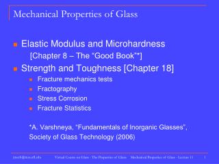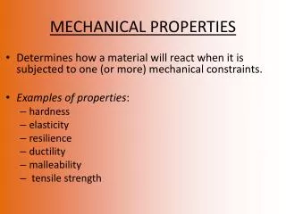
MECHANICAL PROPERTIES
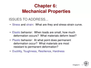
MECHANICAL PROPERTIES. ISSUES TO ADDRESS. • Stress and strain : What are they and why are they used instead of load and deformation?. • Elastic behavior: When loads are small, how much deformation occurs? What materials deform least?.

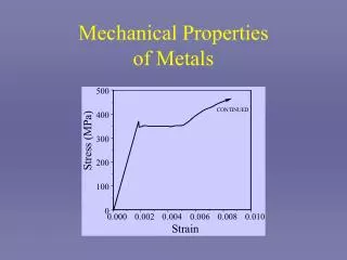
MECHANICAL PROPERTIES
E N D
Presentation Transcript
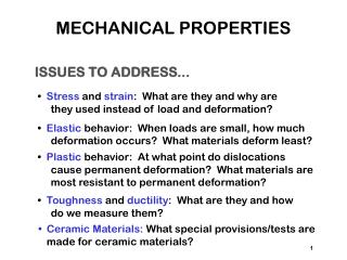
MECHANICAL PROPERTIES ISSUES TO ADDRESS... • Stress and strain: What are they and why are they used instead of load and deformation? • Elastic behavior: When loads are small, how much deformation occurs? What materials deform least? • Plastic behavior: At what point do dislocations cause permanent deformation? What materials are most resistant to permanent deformation? • Toughness and ductility: What are they and how do we measure them? • Ceramic Materials: What special provisions/tests are • made for ceramic materials? 1
ELASTIC DEFORMATION 1. Initial 2. Small load 3. Unload Elastic means reversible! 2
PLASTIC DEFORMATION (METALS) 1. Initial 2. Small load 3. Unload Plastic means permanent! 3
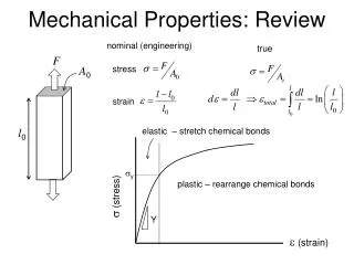
ENGINEERING STRESS • Tensile stress, s: • Shear stress, t: Stress has units: N/m2 or lb/in2 4
ENGINEERING STRAIN • Tensile strain: • Lateral strain: • Shear strain: Strain is always dimensionless. 8
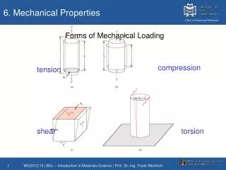
STRESS-STRAIN TESTING • Typical tensile specimen • Typical tensile test machine • Other types of tests: --compression: brittle materials (e.g., concrete) --torsion: cylindrical tubes, shafts. 9
LINEAR ELASTIC PROPERTIES • Modulus of Elasticity, E: (also known as Young's modulus) • Hooke's Law: s = Ee • Poisson's ratio, n: metals: n ~ 0.33 ceramics: ~0.25 polymers: ~0.40 Units: E: [GPa] or [psi] n: dimensionless 10
OTHER ELASTIC PROPERTIES • Elastic Shear modulus, G: simple torsion test t = Gg • Elastic Bulk modulus, K: pressure test: Init. vol =Vo. Vol chg. = DV • Special relations for isotropic materials: 12
YOUNG’S MODULI: COMPARISON Graphite Ceramics Semicond Metals Alloys Composites /fibers Polymers E(GPa) 13
PLASTIC (PERMANENT) DEFORMATION (at lower temperatures, T < Tmelt/3) • Simple tension test: 15
YIELD STRENGTH, sy • Stress at which noticeableplastic deformation has occurred. when ep = 0.002 16
YIELD STRENGTH: COMPARISON Room T values Based on data in Table B4, Callister 6e. a = annealed hr = hot rolled ag = aged cd = cold drawn cw = cold worked qt = quenched & tempered 17
TENSILE STRENGTH, TS • Maximum possible engineering stress in tension. • Metals: occurs when noticeable necking starts. • Ceramics: occurs when crack propagation starts. • Polymers: occurs when polymer backbones are aligned and about to break. 18
TENSILE STRENGTH: COMPARISON Room T values Based on data in Table B4, Callister 6e. a = annealed hr = hot rolled ag = aged cd = cold drawn cw = cold worked qt = quenched & tempered AFRE, GFRE, & CFRE = aramid, glass, & carbon fiber-reinforced epoxy composites, with 60 vol% fibers. 19
DUCTILITY, %EL • Plastic tensile strain at failure: Adapted from Fig. 6.13, Callister 6e. • Another ductility measure: • Note: %AR and %EL are often comparable. --Reason: crystal slip does not change material volume. --%AR > %EL possible if internal voids form in neck. 20
TOUGHNESS • Energy to break a unit volume of material • Approximate by the area under the stress-strain curve. 21
HARDENING • An increase in sy due to plastic deformation. • Curve fit to the stress-strain response: 22
MEASURING ELASTIC MODULUS • Room T behavior is usually elastic, with brittle failure. • 3-Point Bend Testing often used. --tensile tests are difficult for brittle materials. • Determine elastic modulus according to: 23
MEASURING STRENGTH • 3-point bend test to measure room T strength. • Typ. values: • Flexural strength: Si nitride Si carbide Al oxide glass (soda) 700-1000 550-860 275-550 69 300 430 390 69 24
TENSILE RESPONSE: ELASTOMER CASE • Compare to responses of other polymers: --brittle response (aligned, cross linked & networked case) --plastic response (semi-crystalline case) 25
T AND STRAIN RATE: THERMOPLASTICS • Decreasing T... --increases E --increases TS --decreases %EL • Increasing strain rate... --same effects as decreasing T. 26
TIME DEPENDENT DEFORMATION: CREEP • Data: Large drop in Er for T > Tg. • Stress relaxation test: (amorphous polystyrene) --strain to eo and hold. --observe decrease in stress with time. • Relaxation modulus: • Sample Tg(C) values: PE (low Mw) PE (high Mw) PVC PS PC -110 - 90 + 87 +100 +150 27
HARDNESS • Resistance to permanently indenting the surface. • Large hardness means: --resistance to plastic deformation or cracking in compression. --better wear properties. 28
DESIGN OR SAFETY FACTORS • Design uncertainties mean we do not push the limit. • Factor of safety, N Often N is between 1.2 and 4 • Ex: Calculate a diameter, d, to ensure that yield does not occur in the 1045 carbon steel rod below. Use a factor of safety of 5. 5 29
MECHANICAL FAILURE ISSUES TO ADDRESS... • How do flaws in a material initiate failure? • How is fracture resistance quantified; how do different material classes compare? • How do we estimate the stress to fracture? • How do loading rate, loading history, and temperature affect the failure stress? Computer chip-cyclic thermal loading. Hip implant-cyclic loading from walking. Ship-cyclic loading from waves. 1
MODERATELY DUCTILE FAILURE • Evolution to failure: 50 mm 50 mm • Resulting fracture surfaces (steel) 100 mm particles serve as void nucleation sites. 4
BRITTLE FRACTURE SURFACES • Intragranular (within grains) • Intergranular (between grains) 304 S. Steel (metal) 316 S. Steel (metal) 160mm 4 mm Polypropylene (polymer) Al Oxide (ceramic) 3mm 1 mm 5
IDEAL VS REAL MATERIALS TS << TS engineering materials perfect materials • Stress-strain behavior (Room T): • DaVinci (500 yrs ago!) observed... --the longer the wire, the smaller the load to fail it. • Reasons: --flaws cause premature failure. --Larger samples are more flawed! 6
FLAWS ARE STRESS CONCENTRATORS! • Elliptical hole in a plate: • Stress distrib. in front of a hole: • Stress conc. factor: • Large Kt promotes failure: 7
ENGINEERING FRACTURE DESIGN • Avoid sharp corners! 8
WHEN DOES A CRACK PROPAGATE? • rt at a crack tip is very small! • Result: crack tip stress is very large. • Crack propagates when: the tip stress is large enough to make: K ≥ Kc 9
GEOMETRY, LOAD, & MATERIAL • Condition for crack propagation: K ≥ Kc Stress Intensity Factor: --Depends on load & geometry. Fracture Toughness: --Depends on the material, temperature, environment, & rate of loading. • Values of K for some standard loads & geometries: 10
DESIGN AGAINST CRACK GROWTH K ≥ Kc • Crack growth condition: • Largest, most stressed cracks grow first! --Result 2: Design stress dictates max. flaw size. --Result 1: Max flaw size dictates design stress. 12
DESIGN EX: AIRCRAFT WING • Material has Kc = 26 MPa-m0.5 • Two designs to consider... Design B --use same material --largest flaw is 4 mm --failure stress = ? Design A --largest flaw is 9 mm --failure stress = 112 MPa • Use... • Key point: Y and Kc are the same in both designs. --Result: 112 MPa 9 mm 4 mm Answer: • Reducing flaw size pays off! 13
LOADING RATE • Increased loading rate... --increases sy and TS --decreases %EL • Why? An increased rate gives less time for disl. to move past obstacles. • Impact loading: --severe testing case --more brittle --smaller toughness 14
TEMPERATURE • Increasing temperature... --increases %EL and Kc • Ductile-to-brittle transition temperature (DBTT)... 15
DESIGN STRATEGY:STAY ABOVE THE DBTT! • Pre-WWII: The Titanic • WWII: Liberty ships • Problem: Used a type of steel with a DBTT ~ Room temp. 16
FATIGUE • Fatigue = failure under cyclic stress. • Stress varies with time. --key parameters are S and sm • Key points: Fatigue... --can cause part failure, even though smax < sc. --causes ~ 90% of mechanical engineering failures. 17
FATIGUE DESIGN PARAMETERS • Fatigue limit, Sfat: --no fatigue if S < Sfat • Sometimes, the fatigue limit is zero! 18
FATIGUE MECHANISM • Crack grows incrementally typ. 1 to 6 increase in crack length per loading cycle crack origin • Failed rotating shaft --crack grew even though Kmax < Kc --crack grows faster if • Ds increases • crack gets longer • loading freq. increases. 19
IMPROVING FATIGUE LIFE 1. Impose a compressive surface stress (to suppress surface cracks from growing) --Method 1: shot peening --Method 2: carburizing 2. Remove stress concentrators. 20
SUMMARY • Engineering materials don't reach theoretical strength. • Flaws produce stress concentrations that cause premature failure. • Sharp corners produce large stress concentrations and premature failure. • Failure type depends on T and stress: -for noncyclic s and T < 0.4Tm, failure stress decreases with: increased maximum flaw size, decreased T, increased rate of loading. -for cyclic s: cycles to fail decreases as Ds increases. -for higher T (T > 0.4Tm): time to fail decreases as s or T increases. 26
Joint Replacement: Materials, Properties and Implications This diagrams shows seven locations where total joint arthroplasties (TJAs) are currently used to replace poorly functioning joints.
The history of total hip arthroplasty ins particularly to biomaterials science because it is one of the best illustrations of how an implant first used over a century ago has evolved into the highly successful status it has, primarily because of advances in biomaterials.
Table of most common orthopedic biomaterials Examples of the three types of bearing couples used in modern TJA. From top to bottom: metal-on-polymer, ceramic-0n-ceramic, and metal-on-metal.
Approximate weight percent of different metals within popular orthopedic alloys Approximate weight percent of different metals within popular orthopedic alloys Approximate weight percent of different metals within popular orthopedic alloys Electrochemical properties of implant metals (corrosion resistance) in 0.1 M NaCl at pH 7. Electrochemical properties of implant metals (corrosion resistance) in 0.1 M NaCl at pH 7.
Examples of new THA and TKA oxidized zirconium components currently gaining popularity because of enhanced mechanical and biocompatibility properties. Examples of currently used surface coatings on stems of THA to enhance both short- and long-term fixation
Schematic of the interface of a passivating alloy surface in contact with a biological environment Modular junction taper connection of a total hip arthroplasty showing corrosion of the taper connections. Macrograph of deposits of CrPO4 corrosion particle products on the rim of a modular Co-Cr femoral head.
A schematic showing examples of the most common cytokines produced by cells reacting to implant debris acting through a variety of pathways to negatively affect bone turnover. Cytokines are a category of signaling proteins and glycoproteins that, like hormones and neurotransmitters, are used extensively in cellular communication. Cytokines are critical to the development and functioning of both the innate and adaptive immune response. They are often secreted by immune cells that have encountered a pathogen, thereby activating and recruiting further immune cells to increase the system's response to the pathogen.