Chapter 9 Image Registration
Chapter 9 Image Registration. Chuan-Yu Chang ( 張傳育 )Ph.D. Dept. of Computer and Communication Engineering National Yunlin University of Science & Technology chuanyu@yuntech.edu.tw http://mipl.yuntech.edu.tw Office: EB212 Tel: 05-5342601 Ext. 4337. Introduction.


Chapter 9 Image Registration
E N D
Presentation Transcript
Chapter 9Image Registration Chuan-Yu Chang (張傳育)Ph.D. Dept. of Computer and Communication Engineering National Yunlin University of Science & Technology chuanyu@yuntech.edu.tw http://mipl.yuntech.edu.tw Office: EB212 Tel: 05-5342601 Ext. 4337
Introduction • Different medical imaging modalities provide specific information about human physiology and physiological processes that are often complimentary in diagnosis. • To understand the physiological processes better, images obtained from different modalities need to be registered. • To study the variability of anatomical and function structures among the subjects, images from respective modalities can be registered to develop computerized atlases. • Structural Computerized Atlas (SCA) • Represent the anatomical variations among subjects can be developed using registered image from the anatomical medical imaging modalities such as CT or MRI. • Functional Computerized Atlas (FCA) • Represent the metabolic variations among subjects for a specific pathology or function can be developed using registered images from the functional medical imaging modalities such as fMRI, SPECT or PET.
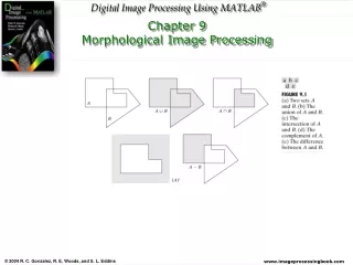
Anatomical Reference (SCA) Reference Signatures Functional Reference (FCA) MR Image (New Subject) MR-PET Registration PET Image (New Subject) Analysis A schematic diagram of multi-modality MR-PET image analysis using computerized atlases.
Introduction • Image registration methods and algorithms provide transformation of a source image space to the target image space. • The target image may be an image of the same or any other subject from any medical imaging modality. • Registration methods • External markers and stereotactic frames based landmark registration. • Rigid-body transformation based global registration. • Image feature-based registration • Boundary and surface matching based registration • Image landmarks and features based registration
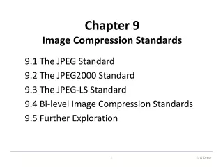
B A f g Image Registration Through Transformation
Rigid-Body Transformation • Rigid-Body Transformation is based on translation and rotation operations. • Two images of equal dimensions are registered by applying a pixel-by-pixel transformation consistently throughout the image space. • A rigid transformation based mapping of a point vector x to x’ is defined bywhere R is a rotation matrix and t is translation vector.
The translation and rotation operations of a 3-D rigid transformation. Translation along x-axis by p Translation along y-axis by q Translation along z-axis by r Rotation by f Translation of z Translation of y Translation of x Rotation by q Rotation by w Rigid-body Transform
The translation and rotation operations of a 3-D rigid transformation. Rotation about x-axis by q Rotation about y-axis by w Rotation about z-axis by f Rotation by f Translation of z Translation of y Translation of x Rotation by q Rotation by w Rigid-body Transform
Rigid-body Transform • The rotation matrix R for the x-y-z rotational order of operation can be given as
Affine Transformation • Affine transformation is a special case of rigid-body transformation that includes translation, rotation and scaling operations. • If the two image volumes to be registered are not at the same scale, a scaling parameter in each dimension has to be added aswhere a, b, and c are the scaling parameters along x, y, and z directions.
Affine Transformation • The affine transformation can be expressed aswhere A is the Affine matrix that includes the translation, rotation and scaling transformation with nine parameters. • The overall mapping can be expressed as
Principal Axes Registration • Principal Axes Registration can be used for global matching of two binary volumes such as segmented brain volumes from CT, MR or PET images. • Let us represent a binary segmented B(x,y,z) as • Let the centroid of the binary volume B(x,y,z) be represented by (xg, yg, zg)T
Principal Axes Registration • The principle axes of B(x,y,z) are the eigenvectors of the inertia matrix I:where • The method can resolve six degrees of freedom of an object including three rotations and three translations.
Principal Axes Registration • Let us define a normalized eigenvector matrix E as • Let R=RaRbRr represent the rotation matrix aswhere a, b, and r are the rotation angles with respect to the x, y, and z axes.
Principal Axes Registration • By equating the normalized eigenvector matrix to the rotation matrix asit can be shown that
Principal Axes Registration • Given two volumes, V1 and V2, for registration, the PAR method provides the following operations: • Translate the centroid of V1 to the origin. • Rotate the principal axes of V1 to coincide with the x, y and z axes. • Rotate the x, y and z axes to coincide with the principal axes of V2. • Translate the origin to the centroid of V2. • The volume V2 is scaled to match the volume V1 using the scaling factor Fs.
Principal axes Transformation Step 1: Define the volume
Principal axes Transformation • Step 3: Computing the principal axes: • The principal axes of V(x,y,z) are the eigenvectors of the inertia matrix I:
Principal axes Transformation The normalized eigenvector matrix E of I is then obtained with
Principal axes Transformation • Step 4: Computing the rotation matrix • The E is expanded to a product of rotation matrix by
Principal axes Transformation • Step 5: Computing the transform matrix • The registration of image 1 to image 2 can be obtained by a translation to the center of mass coordinate system followed by the transform matrix
A 3-D model of brain ventricles obtained from registering 22 MR brain images using the PAR method.
Rotated views of the 3-D brain ventricle model shown in Figure 9.3.
Iterative Principal Axes Registration • The Iterative Principal Axes Registration method can be used with partial volumes. • For registering MR and PET brain images. • The IPAR algorithm allows registration of two 3D image data sets in which one of the data set does not cover the entire volume but has the subvolume contained in the other data set. • Let V1and V2 represent two volumes to be registered, the IPAR method can be implemented using the following steps: • Find the full dynamic range of PET data and select a threshold T, which is about 20% of the maximum gray-level value. Extract binary brain regions using a region growing method on the thresholded PET slice data. • Threshold and extract binary brain regions from the MR data using a region growing method.
Iterative Principal Axes Registration • Stack 2-D binary segmented MR slices and interpolate as necessary to obtain cubic voxel dimensions using a shape-based interpolation algorithm.(3-D binary MR data) • Stack 2-D binary segmented PET slices and interpolate as necessary to obtain cubic voxel dimension to match the voxel dimension of brain MR data using a shape-based interpolation algorithm. .(3-D binary PET data) • Define a Field of View box, FOV(0) as a parallelepiped from the slices of the interpolated binary PET data to cover the PET brain volume • Compute the centroid and principal axes of the binary PET brain volume.
Iterative Principal Axes Registration • IPAR algorithm • Interpolate the gray-level PET data to match the resolution of MR data to prepare the PET data for registration with MR data. • Transform the gray-level PET data into the space of the MR slices using the last set of MR and PET centroids and principal axes. Extract the slices from the transformed gray-level PET data that match the gray-level MR image.
Iterative Principal Axes Registration • The IPAR algorithm • For i =n to 0 do • Compute the centroid and principal axes of the current binary MR brain volume. • Transform the augmented FOV (i) box according to the space of the MR slices • The PET data are registered with the MR data by performing the required translations and rotations • Translate the centroid of the binary PET data to origin. • Rotate the principal axes of the binary PET data to coincide with the x, y and z axes. • Rotate the x, y and z axes to coincide with the MR principal axes. • Translate the origin to the centroid of the binary MR data. • Remove all voxels of the binary MR brain which lie outside the transformed FOV(i) box.
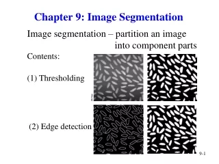
Iteration 1 Iteration 2 • Three successive iterations of the IPAR algorithms for registration of vol 1 and vol 2: The results of the first iteration (a), the second iteration (b) and the final iteration (c). Vol 1 represents the MR data while the PET image with limited filed of view (FOV) is represented by vol 2.
Sequential slices of MR (middle rows) and PET (bottom rows) and the registered MR-PET brain images (top row) of the corresponding slices using the IPAR method.
Sequential slices of MR (middle rows) and PET (bottom rows) and the registered MR-PET brain images (top row) of the corresponding slices using the IPAR method.
Sequential slices of MR (middle rows) and PET (bottom rows) and the registered MR-PET brain images (top row) of the corresponding slices using the IPAR method.
Image Landmarks and Features based Registration • Once the corresponding landmarks or features are identified from in source and target image spaces, a customized transformation can be computed for registering the source image into the target image space. • Relationships of corresponding points • Relationships of corresponding feature such as surface
Similarity Transformation for Point-Based Registration • Assume that x and y are the corresponding points in the source and target image spaces belonging to the source X and target Y images. • A non-rigid transformation T(x) for registering the source image into the target image space can be defined by a combination of rotation, translation and scaling operations to provide x’ from x assuch that the registration error E is minimized aswhere r, s and t represent the rotation, scaling and translation operations.
Similarity Transformation for Point-Based Registration • A transformation should be obtained with r, s and t values to minimize the error function aswhere wis are the weighting factors representing the confidence in the specific landmark (point) or feature correspondence and N is the total number of landmarks.
Similarity Transformation for Point-Based Registration • To register the source image into the target image space • Set s=1 • Find r through the following steps • Compute the weighted centroid of the body representing the set of landmarks in each spaces as • Compute the distance of each landmark from the centroid as
Similarity Transformation for Point-Based Registration • Compute the weighted co-variance matrix aswith a singular value decomposition aswhere UtU=VtV=Iand • Compute
Similarity Transformation for Point-Based Registration • Compute the scaling factor • Compute the translation factor
Point-Based Registration R is a 3x3 rotation matrix, t is a 3x1 translation vector, p is a 3x1 position vector. <=Orthogonal Procrustes
Surface-Based Registration • Outlining contours on the serial slices of each scan. • Head is a stack of disks or “prisms”, each of which has cross section determined by one of the contour. • Hat is represented as a set of independent points.
Weighted Feature Based Registration • Different optimization functions can be designed to improve the computation of parameters of transformation for registration of the source image into the target image space. • A disparity function can be designed aswhere {Xi} for I = 1, 2, 3, …, N represents a set of corresponding data shapes in x and y spaces. • The transformation T must minimize the disparity function register the source image into the target space utilizing the correspondence of geometrical features.
Weighted Feature Based Registration • Determine the parameters for a rigid or non-rigid body transformation T. • Initialize the transformation optimization loop for k=1 as • For each shape Xiin the source space, find the closest points in the corresponding shape in the target space Yiaswhere Ciis the corresponding function.
Weighted Feature Based Registration • Compute the transformation between {xij(0)} and {yij(k)} with the weights {wij}. • Use the transformation parameters for registration of the corresponding points as • Compute the disparity measure difference d(T(k))-d(T(k+1)), if the convergence criterion is met, stop; otherwise increment k and go to step 3 for next iteration.
Point-Based Registration • Determinate the coordinates of corresponding points in different images, and the estimation of the geometrical transformation using these corresponding point. • Intrinsic points: anatomic landmark • Extrinsic points: artificially applied markers
Surface-Based Registration The general approach is to search iteratively for the rigid-body transformation T that minimizes the cost function: is a point on the surface X C is a correspondence function.
Surface-Based Registration(2) • Coarse registration: Principal axes Transformation • Fine registration: surface fitting • A rigid body is determined by the position of its center of mass and its orientation with respect to its center of mass (principal axes) • Compute the centroid and the three principal axes for a 3-D volume data
Surface fitting based on (E-Distance Transformation) • The DT is performed on the 1st surface images (base image) • base image 2nd surface image (match image) • to determine the registration parameters
Surface fitting based on (E-Distance Transformation) DQ is the distance map of the base image Q pn is the nth point of match image P
ICP Registration algorithm • Iterative Closest Point, ICP 1. assigning one shape to be the “data” shape 2. assigning other shape to be the “model” shape 3. The “data” shape is decomposed into a point set 4.The “data” shape is registered to the “model” shape by iteratively finding “model” points closest to the “data” primitives. • ICP registration method defines the “corresponding” point yj to be the “closest” point on the surface
Volume-Based Registration • 1. Roger P. Woods, Simon R. Cherry, and John C. Mazziotta, ”Rapid automated algorithm for aligning and reslicing PET images”, Journal of Computer Assisted Tomography, 16(4): 620-633, 1992. • 2. Roger P. Woods, John C. Mazziotta, and Simon R. Cherry, ”MRI-PET registration with automated algorithm”, Journal of Computer Assisted Tomography, 17(4): 536-546, 1993.