Download
1 / 23
340 likes | 1.17k Vues
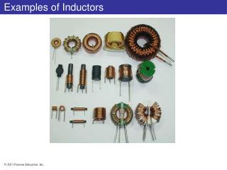
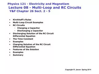
Physics 121 - Electricity and Magnetism Lecture 08 - Multi-Loop and RC Circuits Y&F Chapter 26 Sect. 2 - 5. Kirchhoff’s Rules Multi-Loop Circuit Examples RC Circuits Charging a Capacitor Discharging a Capacitor Discharging Solution of the RC Circuit Differential Equation

E N D
Physics 121 - Electricity and MagnetismLecture 08 - Multi-Loop and RC Circuits Y&F Chapter 26 Sect. 2 - 5 • Kirchhoff’s Rules • Multi-Loop Circuit Examples • RC Circuits • Charging a Capacitor • Discharging a Capacitor • Discharging Solution of the RC Circuit Differential Equation • The Time Constant • Examples • Charging Solution of the RC Circuit Differential Equation • Features of the Solution • Examples • Summary
i1 i i2 Generating Circuit Equations with Kirchhoff’s Loop and Junction Rule • Name currents or other unknowns • Apply Junction Rule • Special Rules for Applying Loop Rule: • Assign either current direction in every branch; negative result opposite flow • Choose direction for traversing a closed loop • traverse branches with or against assumed current direction • Across resistances: • voltage drop DV = - iR when following assumed current • voltage change DV = +iR when traversing opposite to assumed current • When crossing EMFs from – to +, DV = +E. Otherwise DV= -E • After solving, calculate power or other quantities as needed • Dot product i.E determines whether EMFs supply or dissipate power Kirchhoff’s Rules: • Branch/Junction Rule (charge conservation): • The current through all series elements in a • branch is the same. At any junction: • Loop Rule (energy conservation): • The net change in potential difference is • zero for any closed path around a circuit: • Use rules to generate then solve N independent equations in N unknowns
Equivalent resistance for resistors in series Junction Rule: The current through all of the resistances in series (a single branch) is identical: Loop Rule: The sum of the potential differences around a closed loop equals zero: The equivalent circuit replaces the series resistors with a single equivalent resistance: same E, same i as above The equivalent resistance for a series combination is the sum of the individual resistances and is always greater than any one of them. inverse of series capacitance rule
Equivalent resistance for resistors in parallel Loop Rule: The potential differences across each of the parallel branches are the same. i not in these equations Junction Rule: The sum of the currents flowing in equals the sum of the currents flowing out. Combine equations for all the junctions at “a” (same at “b”). The equivalent circuit replaces the series resistors with a single equivalent resistance: same E, same i as above The reciprocal of the equivalent resistance for a parallel combination is the sum of the individual reciprocal resistances and is always smaller than any one of them. inverse of parallel capacitance rule
i i R1= 10 W E2 = 3 V E1 = 8 V R2= 15 W + + - - A battery (EMF) absorbs power (charges up) when I is opposite to E -3.0x0.2 EXAMPLE: MULTIPLE BATTERIES SINGLE LOOP
E1 E2 + - R1 R3 R2 + - B A C D F E Apply Procedure: • Identify branches & junctions. Name all currents (3) and other variables. • Same current flows through all elements in any series branch. • Assume arbitrary current directions; negative result means opposite direction. • Find junctions, write Junction Rule equations for all. i1 i3 i2 • Same equation at junctions A and B (not independent). • Junction Rule yields only 1 of 3 equations needed • Are points C, D, E, F junctions? (No) Example: Multi-loop circuit with 2 EMFs • Given all resistances and EMFs in circuit: • Find currents (i1, i2, i3), then potential • drops and power dissipated by resistors • 3 unknowns (currents) • imply 3 independent equations needed
+ - E1 E2 R1 R3 R2 + - A C B E F D Loop equations for the example circuit: • Only 2 of these three are independent • Now have 3 equations in 3 unknowns ADCBA - CCW ADCBFEA - CCW i3 i1 ABFEA - CCW i2 Procedure, continued: • Apply Loop Rule as often as needed to find • equations that include all the unknowns (3). • Traversal direction is arbitrary. • IR’s are voltage drops when following the assumed • current direction: use - iR • IR’s are steps up when going against assumed current • EMF’s are positive when traversed from – to + side • EMF’s are negative when traversed from + to - sides Solution: (after a lot of algebra) Define:
LOOP RULE: ABCDA - CW CEFDC - CW EGHFE - CW CHECK: POWER: Example: find currents, voltages, power 6 BRANCHES 6 CURRENTS. • JUNCTION RULE: Branches C,E,G are the same point, as are D, F, H. 4 currents left. • Remaining 2 junction equations are dependent • 1 junction equation
Multiple EMF Example: find currents, voltages, power JUNCTION RULE at A & B: LOOP ACDBA: LOOP BFEAB: USE JUNCTION EQUATION: For power use: EVALUATE NUMERICALLY: R2 = 4 W R1 = 2 W E2 = 6 V E1 = 3 V MULTIPLE EMF CIRCUIT USE THE SAME RULES
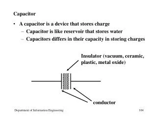
RC Circuits: Time dependance i a • Given Capacitance + Resistance + EMF • Loop Rule + Junction Rule R + • Find Q, i, Vc, U for capacitor • as functions of time E Vc b - C + i - • Assume current i through R is clockwise • Vcap Eas t infinity • Expect zero current as t infinity • Expect largest current at t = 0, • Energy is stored in C, some is dissipated in R Charging: Switch to “a”. Loop equation: Discharging: Switch to “b”. no EMF, Loop equation: • Energy stored in C now dissipated in R • Arbitrarily assume current is still CW • Vcap= Eat t =0, but it must die away • Q0= full charge = CE • Result: i through R is actually CCW 27.8 Can constant current flow through a capacitor indefinitely? First charge up C (switch to “a”) then discharge (switch to “b”)
Q0 Q t 2t 3t t Voltage across C also decays exponentially: Current also decays exponentially: RC Circuit: solution for discharging Circuit Equation: Loop Equation is : Substitute : First order differential equation, form is Q’ = -kQ Exponential solution Charge decays exponentially: • t/RC is dimensionless RC = t = the TIME CONSTANT Q falls to 1/e of original value
RC is constant RC = time constant = time for Q to fall to 1/e of its initial value Time t 2t 3t 4t 5t Value e-1 e-2 e-3 e-4 e-5 % left 36.8 13.5 5.0 1.8 0.67 After 3-5 time constants the action is over Solving for discharging phase by direct integration Initial conditions (“boundary conditions”) exponentiate both sides of above right exponential decay
Units for RC 8-1: We defined = RC, which of the choices best conveys the physical units for the decay constant ? [] = [RC] =[(V/i)(Q/V)]=[Q/Q/t]=[t] • F (ohmfarad) • C/A (coulomb per ampere) • C/V (ohmcoulomb per volt) • VF/A (voltfarad per ampere) • s (second)
a) When has the charge fallen to half of it’s initial value Q0? set: take log: b) When has the stored energy fallen to half of its original value? recall: and where at any time t: evaluate for: take log: c) How does the power delivered by C vary with time? power: C supplies rather than absorbs power Drop minus sign recall: power supplied by C: Examples: discharging capacitor C through resistor R
Solution: Charge starts from zero, grows as a saturating exponential. Qinf Q • RC = t = TIME CONSTANT • describes time dependance again • Q(t) 0 as t 0 • Q(t) Qinf as t infinity t 2t 3t t RC Circuit: solution for charging Circuit Equation: Loop Equation is : Substitute : • First order differential equation again: form is Q’ = - kQ + constant • Same as discharge equation, but i0 = E/ R is on right side • At t = 0: Q = 0 & i = i0. Large current flows (C acts like a plain wire) • As t infinity: Current 0 (C acts like a broken wire) • Q Qinf = CE = same as Q0 for discharge
Current in the charging circuit: Current decays exponentially just as in discharging case Growing potential Vc on C blocks current completely at t = infinity At t=0 C acts like a wire. At t=infinity C acts like a broken wire Voltage drop VR across the resistor: Voltage across R decays exponentially, reaches 0 as t infinity Form factor: 1 – exp( - t / t ) After 3-5 time constants the action is over Factor .63 .865 .95 .982 .993 .998 Time t 2t 3t 4t 5t 6t RC Circuit: solution for charging, continued Voltage across C while charging: Voltage across C also starts from zero and saturates exponentially
RC circuit – multiple resistors 8-2: Consider the circuit shown, The battery has no internal resistance. The capacitor has zero charge. Just after the switch is closed, what is the current through the battery? • 0. • /2R. • 2/R. • /R. • impossible to determine C R R
RC circuit – multiple resistors 8-3: Consider the circuit shown. The battery has no internal resistance. After the switch has been closed for a very long time, what is the current through the battery? • 0. • /2R. • 2/R. • /R. • impossible to determine C R R
Use: Set: Take natural log of both sides: Define: 1 MW = 106W Discharging Example: A 2 mF capacitor is charged and then connected in series with a resistance R. The original potential across it drops to ¼ of it’s starting value in 2 seconds. What is the value of the resistance?
E b) When does VCap (voltage on C) reach 1 Volt? c) Find the current in the resistor at that time Example: Discharging C = 500 mF R = 10 KW V0 = E = 12 V Capacitor C is charged for a long time, then discharged. a) Find current at t = 0
Charging Example: How many time constants does it take for an initially uncharged capacitor in an RC circuit to become 99% charged? Use: Require: Take natural log of both sides: Did not need specific values of RC
R E C b) What’s the current through R at t = 2 sec? Example: Charging a 100 mF capacitor in series with a 10,000 W resistor, using EMF E= 5 V. • How long after voltage is applied does Vcap(t) reach 4 volts? Take natural log of both sides:
Second: Close switch for a long time At equilibrium, current i3 though capacitor zero Find outer loop current i = i1 = 12 using loop rule Now find Voltage across C, same as voltage across right hand branch Final charge on C: Example: Multiple loops and EMFs • Switch S is initially open for a long • time. • Capacitor C charges to potential of battery 2 • S is then closed for a long time What is the CHANGE in charge on C? First: E2 charges C to have: