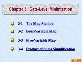
Chapter3: Gate-Level Minimization Part 2
Chapter3: Gate-Level Minimization Part 2. Originally Reham S. Al-Majed. Outline. Don’t-Care Conditions NAND – NOR implementation . Exclusive-OR Function. Don’t Care Conditions. Minterms associated with a function specifies the conditions under which the function is equal to 1.


Chapter3: Gate-Level Minimization Part 2
E N D
Presentation Transcript
Chapter3: Gate-Level MinimizationPart 2 Originally Reham S. Al-Majed Imam Muhammad Bin Saud University
Outline • Don’t-Care Conditions • NAND – NOR implementation. • Exclusive-OR Function
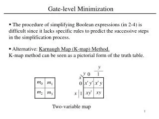
Don’t Care Conditions • Minterms associated with a function specifies the conditions under which the function is equal to 1. • The function is equal to 0 for the rest. • In some applications, the function is not specified for certain combinations of the variables (e.g. BCD) • Incompletely specified functions: are functions that have unspecified outputs for some input combinations. • Unspecified minterms of a function are called don’t-care conditions
Don’t Care Conditions (cont.) • Don’t-care conditions can be used for further simplification. • Marked with an X in the map. • In choosing adjacent squares to simplify the function in a map, the don’t-care minterms may be assumed to be either 0 or 1. • Example: Simplify the Boolean function: F(w,x,y,z) = ∑(1,3,7,11,15) d(w,x,y,z)= ∑(0,2,5) F=yz+w’x’ F=yz+w’z
NAND-NOR Implementation • Digital circuits uses NAND or NOR rather than AND and OR gates. • Easier to fabricate with electronic components and are the basic gates used in all IC digital logic families. • They are called universal gates • Any Boolean function can be implemented with them.
NAND Circuit • The NAND gate represents the complement of the AND operation • Abbreviation of Not AND • Two equivalent graphic symbols for the NAND gate: • Can implement any digital systems. NOT Gate AND Gate OR Gate
NAND Circuit (Cont.) • The implementation of Boolean functions with NAND gate requires that the function be in SoP form • Procedure : • Simplify and express the function in SoP. • Draw a NAND gate for each product term containing at least 2 literal. ( first-level gates) • Draw single NAND gate in the second level with outputs of first-level gates. • A term with a single literal requires inverter.
Example • Implement the following functions with NAND gates F= AB+CD
Multilevel NAND Circuits • If we choose to implement the function as a mixed notation (without reducing the expression into a SoP form) • The procedure is • to change every AND gate to an AND-invert graphic symbol • and every OR gate to an invert-OR symbol . • Make sure that there are two bubbles along the same line
Example Implement the following functions with NAND gates. F = A(CD + B)+ B C’ F = (AB+ AB )(C+D) (page 109-110)
NOR Implementation • The NOR gate represents the complement of the OR operation • Abbreviation of Not OR • Two graphic symbols • Can implement any digital systems
NOR Circuit (Cont.) • A two-level implementation with NOR gate requires that the function be simplified into PoS form • Procedure : • Simplify and express the function in SoP. • Draw a NOR gate (OR-invert symbol) for each sum term containing at least 2 literal. ( first-level gates) • Draw single NOR gate (invert-AND symbol)in the second level with outputs of first-level gates. • A term with a single literal requires inverter.
Example Implement the following function with NOR gates. F = (A + B)(C + D)E
Multilevel NOR Circuits • The procedure for converting a multilevel AND-OR diagram to an all-NOR diagram is • to change every AND gate to an invert-AND graphic symbol • and every OR gate to an OR-invert symbol . • Make sure that there are two bubbles along the same line
Example Implement the following functions with NOR gates. F = (AB+ AB )(C+D) (page 111)
(XOR)Exclusive-OR function x 0 = x x 1 = x x x = 0 x x = 1 Commutative and associative
XOR implementation • A two-input XOR function is constructed with conventional gates Or with NAND gates
Odd Function Figure 2.8 3-input XOR gate • The multiple- variable XOR is an odd function: it is equal to 1 if the inputs variables have an odd number of 1's. • Example : Three variables F = (1,2,4,7)
(XOR)Exclusive-OR function Only a limited number of Boolean functions can be expressed in terms of XOR operations. Nevertheless, this function is particularly useful in arithmetic operations ,error detection and correction circuits. Parity Generation and Checking (page num 120)
Reading • 3.1 • 3.2 • 3.3 • 3.5 • 3.6 • 3.7 • 3.9