Effective Phasing Techniques for Energy Recovery Linacs: Overview and Applications
Phasing control is crucial for the successful operation of Energy Recovery Linacs (ERLs), enabling optimal bunch length and energy spread compression. By understanding the relationship between RF phase and energy gain, operators can set phases to maximize performance. This involves measuring energy via spectrometers and managing various components like beam offsets and misalignments. Techniques such as gang phasing, spatial transformations, and monitoring beam behavior are essential for overcoming challenges and enhancing overall system efficiency during both recovery and acceleration phases.

Effective Phasing Techniques for Energy Recovery Linacs: Overview and Applications
E N D
Presentation Transcript
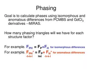
Overview • Phase control very important for successful operation of ERL – must have “right” phase to get both bunch length compression at FEL & energy spread compression at dump =>Need to know where beam is timed relative to RF waveform • Basic idea to get this information is simple: energy gain from a cavity is a function of RF phase • To set the phase to “crest”, maximize the energy gain • Use calibrated RF drive controls to set phase offsets => Need a way to measure energy…
Spectrometer Design • Again, idea is notionally simple: • bend angle is a function of energy • vary phase => vary energy => vary bending • “just” look at bend to determine crest • Sadly, life ain’t simple: cavities steer as well as accelerate; the steering is phase dependent: • Beam offsets in focusing fields/cavity misalignments • Coupler (HOM and FP) kicks these can dominate at low energy (as in our injector) high-energy orbit reference (on-energy) orbit low-energy orbit
How to disentangle? • Need a means of sorting out betatron motion from energy • Can monitor beam behavior in nondispersed location (betatron component), propagate forward/backward to dispersed location & extract betatron portion of motion • Need machine model, software, lots of symmetry, … or,… • can impose (or notice) symmetries available in dispersed region and save some effort
( Bates Bend as a Spectrometer • Transport from cavity -> start of 180o dipole in Bates bend: • Output position depends on cavity steering and energy - both are phase-dependent: • Transport from cavity through 180o dipole in Bates bend: • Betatron part of output flips sign: • Average of readings depends on energy deviation only:
IPM5F03 DC Gun • Basic trick: use dispersed beamline with –I spatial transform between a pair of observation points; • average of results from the two observations cancels steering effects • In our ERL, we have BPMs immediately upstream/downstream of the 180o dipoles & provide the position reading and their average on the BPM displays • IPM2F07, IPM2F09 <x2F08>, IPM5F01, IPM5F03 <x5F02> • <x> is direct measure of dp/p IR Wiggler IPM5F01 SRF Linac Bunching Chicane UV FEL Transport Line Dump IPM2F07 IPM2F09
Phasing Process – Individual Cavities • Waveform is cosine, but witharbitrary (and possibly slowly varying) phase offset depending on cables, gallery temperature, market forces, demons… • Vary phase while watching <x> to establish phase fcrestat which maximum position occurs • Position is symmetric around crest phase (cosine function) • Crest phase is midpoint between symmetric offsets from maximum fcrest =(f1+f2)/2 <x> xreference xo Df f f1 f0 f2 -180o 180o
Cryomodule Gang Phase • Energy after a cryomodule is a sum of individual cavity gains and is affected by remnant phasing errors • Can include systematic “gang phase” – add/subtract same phase offset for all cavities – to eliminate residual • Suppresses phasing errors and allows you to set systematic offset for all cavities (e.g. for chirp) • Also provides diagnostic for individual cavity phase • when gang phase wanders away from nominal value (with energy more or less constant), all phases are likely drifting systematically due to environmental changes such as zone-to-zone cabling-driven drifts • When gang phase wanders and energy drops, cavity phases are wandering off from crest randomly • Gang phasing done same way as cavity phasing: • Pick an offset gang phase (e.g. 10o) • Set reference position at offset (e.g., zero BPMs) • Move gang phase to maximize offset, then back to reference value • “Crest” gang phase is then midpoint (average) of the two phases
Phasing for Energy Recovery: Path Length DC Gun • Energy recovered beam phase is set by recirculator path length, which is controlled by steering trims in end of pi-bends • Vary trims to set final energy to dump line set-point & deliver beam cleanly to beam dump • dump line serves as spectrometer IR Wiggler SRF Linac Bunching Chicane UV FEL Transport Line Dump
Phasing the Linac Using ONLY the Linac- Transient Phasing • During initial beam threading (either acceleration or recovery) you often can’t get beam to a spectrometer – need another means of phasing • Can use beam loading to (roughly) determine timing of beam relative to cavity RF field • RF drive/controls (“GASK”) tell you if the beam is drawing power from a cavity • For single pass, can find 0-crossing & step beam to crest by moving phase 90o – just look at gradient request and dial phase until it vanishes • For two passes, can (roughly) set path length for full energy recovery (beams 180o out of phase) by setting 2nd pass timing to eliminate beam loading – just watch gradient request and vary path length to zero it