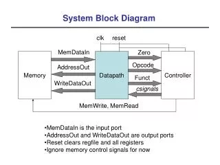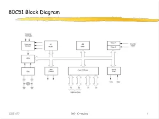
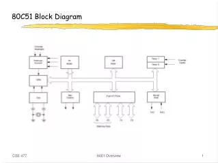
80C51 Block Diagram
80C51 Block Diagram. 80C51 Memory. 8051 Memory. The data width is 8 bits Registers are 8 bits Addresses are 8 bits i.e. addresses for only 256 bytes! PC is 16 bits (up to 64K program memory) DPTR is 16 bits (for external data - up to 64K) C types

80C51 Block Diagram
E N D
Presentation Transcript
80C51 Block Diagram 8051 Overview
80C51 Memory 8051 Overview
8051 Memory • The data width is 8 bits • Registers are 8 bits • Addresses are 8 bits • i.e. addresses for only 256 bytes! • PC is 16 bits (up to 64K program memory) • DPTR is 16 bits (for external data - up to 64K) • C types • char - 8 bits <-- use this if at all possible! • short - 16 bits • int - 16 bits • long - 32 bits • float - 32 bits • C standard signed/unsigned 8051 Overview
Accessing External Memory 8051 Overview
Program Memory • Program and Data memory are separate • Can be internal and/or external • 20K internal flash for the Atmel controller • Read-only • Instructions • Constant datachar code table[5] = {‘1’,‘2’,‘3’,‘4’,‘5’} ; • Compiler uses instructions for moving “immediate” data 8051 Overview
External Data Memory • External Data - xdata • Resides off-chip • Accessed using the DPTR and MOVX instruction • We will not use xdata • We will use the SMALL memory model • all data is on-chip • limited to only ~128 bytes of data! 8051 Overview
Internal Data Memory • Internal data memory contains all the processor state • Lower 128 bytes: registers, general data • Upper 128 bytes: • indirectly addressed: 128 bytes, used for the stack (small!) • directly addressed: 128 bytes for “special” functions 8051 Overview
Lower 128 bytes • Register banks, bit addressable data, general data • you can address any register! • let the C compiler deal with details (for now) 8051 Overview
Data Memory Specifiers • “data” - first 128 bytes, directly addressed • the default • “idata” - all 256 bytes, indirectly addressed (slower) • “bdata” - bit-addressable memory • 16 bytes from addresses 0x20 to 0x2F • 128 bit variables maxbit flag1, flag2; flag1 = (a == b); • can access as bytes or bitschar bdata flags; sbit flag0 = flags ^ 0; /* use sbit to “overlay” */ sbit flag7 = flags ^ 7; /* ^ specifies bit */ flags = 0; /* Clear all flags */ flag7 = 1; /* Set one flag */ 8051 Overview
Upper 128 bytes: SFR area 8051 Overview
Accessing SFRs • The interesting SFRs are bit-addressable • addresses 0x80, 0x88, 0x90, . . . , 0xF8 • SFRs can be addressed by bit, char or int sbit EA = 0xAF; /* one of the interrupt enables sfr Port0 = 0x80; /* Port 0 */ sfr16 Timer2 = 0xCC; /* Timer 2 */ sbit LED0 = Port1 ^ 2; /* Define a port bit */ EA = 1; /* Enable interrupts */ Port0 = 0xff; /* Set all bits in Port 0 to 1 if (Timer2 > 100) . . . LED0 = 1; /* Turn on one bit in Port 2 */ 8051 Overview
Ports • Port 0 - external memory access • low address byte/data • Port 2 - external memory access • high address byte • Port 1 - general purpose I/O • pins 0, 1 for timer/counter 2 • Port 3 - Special features • 0 - RxD: serial input • 1 - TxD: serial output • 2 - INT0: external interrupt • 3 - INT1: external interrupt • 4 - T0: timer/counter 0 external input • 5 - T1: timer/counter 1 external input • 6 - WR: external data memory write strobe • 7 - RD: external data memory read strobe 8051 Overview
Ports 8051 Overview
Ports • Port 0 - true bi-directional • Port 1-3 - have internal pullups that will source current • Output pins: • Just write 0/1 to the bit/byte • Input pins: • Output latch must have a 1 (reset state) • Turns off the pulldown • pullup must be pulled down by external driver • Just read the bit/byte 8051 Overview
Program Status Word • Register set select • Status bits 8051 Overview
Instruction Timing • One “machine cycle” = 6 states (S1 - S6) • One state = 2 clock cycles • One “machine cycle” = 12 clock cycles • Instructions take 1 - 4 cycles • e.g. 1 cycle instructions: ADD, MOV, SETB, NOP • e.g. 2 cycle instructions: JMP, JZ • 4 cycle instructions: MUL, DIV 8051 Overview
Instruction Timing 8051 Overview
Timers • Base 8051 has 2 timers • we have 3 in the Atmel 89C55 • Timer mode • Increments every machine cycle (12 clock cycles) • Counter mode • Increments when T0/T1 go from 1 - 0 (external signal) • Access timer value directly • Timer can cause an interrupt • Timer 1 can be used to provide programmable baud rate for serial communications • Timer/Counter operation • Mode control register (TMOD) • Control register (TCON) 8051 Overview
Mode Control Register (TMOD) • Modes 0-3 • GATE - allows external pin to enable timer (e.g. external pulse) • 0: INT pin not used • 1: counter enabled by INT pin (port 3.2, 3.3) • C/T - indicates timer or counter mode 8051 Overview
Timer/Counter Control Register (TCON) • TR - enable timer/counter • TF - overflow flag: can cause interrupt • IE/IT - external interrupts and type control • not related to the timer/counter 8051 Overview
Timer/Counter Mode 0 • Mode 1 same as Mode 0, but uses all 16 bits 8051 Overview
Timer/Counter Mode 2 • 8-bit counter, auto-reload on overflow 8051 Overview
Timer/Counter Mode 3 • Applies to Timer/Counter 0 • Gives an extra timer 8051 Overview
Interrupts • Allow parallel tasking • Interrupt routine runs in “background” • Allow fast, low-overhead interaction with environment • Don’t have to poll • Immediate reaction • An automatic function call • Easy to program • 8051 Interrupts • Serial port - wake up when data arrives/data has left • Timer 0 overflow • Timer 1 overflow • External interrupt 0 • External interrupt 1 8051 Overview
Interrupt Vector • For each interrupt, which interrupt function to call • In low program addresses • Hardware generates an LCALL to address in interrupt vector • Pushes PC (but nothing else) onto the stack • RETI instruction to return from interrupt 0x00 - Reset PC address 0: 0x03 - External interrupt 0 1: 0x0B - Timer 0 2: 0x13 - External interrupt 1 3: 0x1B - Timer 1 4: 0x23 - Serial line interrupt 8051 Overview
Writing Interrupts in C • The C compiler takes care of everything • Pushing/popping the right registers (PSW, ACC, etc.) • Generating the RTI instruction • No arguments/no return valuesunsigned int count;unsigned char second;void timer0 (void) interrupt 1 using 2 { if (++count == 4000) { second++; count = 0; }} • Timer mode 2 • Reload value = 6 8051 Overview
Timer Interrupts • Wakeup after N clock cycles, i.e. at a specified time • Wakeup every N clock cycles (auto reload) • Allows simple task scheduling • Clients queue function calls for time i • Interrupt routine calls functions at the right time • Wakeup after N events have occurred on an input 8051 Overview
Design Problem 1 - frequency counter • Measure the frequency of an external signal • Display as a number using the 7-segment display • e.g. number represents exponent of 2 or 10 8051 Overview
Example Timer Setup • What does this setup do? TMOD = 0x62; // 01100010; TCON = 0x50; // 01010000; TH1 = 246; TH0 = 6; IE = 0x8A; // 10001010; 8051 Overview
Using the timers void counterInterrupt ( void ) interrupt 3 using 1 { timeLow = TL0; TL0 = 0; timeHigh = count; count = 0; if (timeHigh == 0 && timeLow < 10) *ledaddress = 0x6f; else if (timeHigh == 0 && timeLow < 100) *ledaddress = 0x6b; else if (timeHigh < 4) *ledaddress = 0x02; else if (timeHigh < 40) *ledaddress = 0x04; else if (timeHigh < 400) *ledaddress = 0x08; else if (timeHigh < 4000) *ledaddress = 0x10; else if (timeHigh < 40000) *ledaddress = 0x20; else *ledaddress = 0xf0; // default } void timerInterrupt ( void ) interrupt 1 using 1 { count++; } 8051 Overview
Design Problem 2 - Measure the pulse width • Problem: send several bits of data with one wire • Serial data • precise, but complicated protocol • Pulse width • precise enough for many sensors • simple measurement 8051 Overview
Design Problem 3 - Accelerometer Interface • Accelerometer • Two signals, one for each dimension • Acceleration coded as the duty cycle • pulse-width/cycle-length • cycle time = 1ms - 10ms (controlled by resistor) • 1ms gives faster sampling • 10ms gives more accurate data 8051 Overview
Controlling Interrupts: Enables and Priority 8051 Overview
Interrupt Controls 8051 Overview
Interrupt Priorities • Two levels of priority • Set an interrupt priority using the interrupt priority register • A high-priority interrupt can interrupt an low-priority interrupt routine • In no other case is an interrupt allowed • An interrupt routine can always disable interrupts explicitly • But you don’t want to do this • Priority chain within priority levels • Choose a winner if two interrupts happen simultaneously • Order shown on previous page 8051 Overview
Re-entrant Functions • A function can be called simultaneously be different processes • Recursive functions must be re-entrant • Functions called by interrupt code and non-interrupt code must be re-entrant • Keil C functions by default are not re-entrant • Does not use the stack for everything • Use the reentrant specifier to make a function re-entrantint calc (char i, int b) reentrant { int x; x = table[i]; return (x * b);} 8051 Overview
External Interrupts • Can interrupt using the INT0 or INT1 pins (port 3: pin 2,3) • Interrupt on level or falling edge of signal (TCON specifies which) • Pin is sampled once every 12 clock cycles • for interrupt on edge, signal must be high 12 cycles, low 12 cycles • Response time takes at least 3 instuctions cycles • 1 to sample • 2 for call to interrupt routine • more if a long instruction is in progress (up to 6 more) 8051 Overview