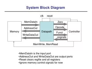
EFI Block Diagram
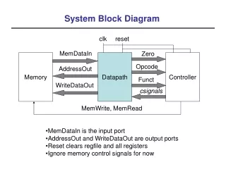
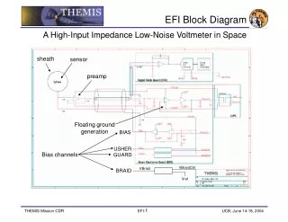
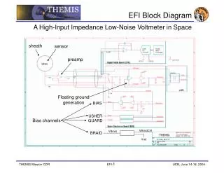
EFI Block Diagram. A High-Input Impedance Low-Noise Voltmeter in Space. sheath. sensor. preamp. Floating ground generation. BIAS. USHER. Bias channels. GUARD. VBraidCtrl. VBraid. BRAID. Vref. Top-Level Design (1). Diagram of THEMIS EFI Elements. AXB. Preamp Enclosure.

EFI Block Diagram
E N D
Presentation Transcript
EFI Block Diagram • A High-Input Impedance Low-Noise Voltmeter in Space sheath sensor preamp Floating ground generation BIAS USHER Bias channels GUARD VBraidCtrl VBraid BRAID Vref
Top-Level Design (1) • Diagram of THEMIS EFI Elements AXB Preamp Enclosure Preamp PWB BEB SPB DFB GSE
Top-Level Design (2) • Description of THEMIS EFI Elements • Three-axis E-field measurement, drawing on 30 years of mechanical and electrical design heritage at UCBSSL. • Closest living relatives are Cluster, Polar and FAST, with parts heritage from CRRES (mechanical systems, BEB designs, preamp designs).
Top-Level Design (3) • Description of THEMIS EFI Elements • Radial booms: • 22-m cable length (up to 50 m tip-to-tip deployed; SPB-X to be deployed to 50 m, SPB-Y to be deployed to 40 m). • 8-cm dia., Ti-N-coated spherical sensor. • 3-m, 0.009-inch dia. fine wire to preamp enclosure. • SMA-actuated door release mechanism. • Brushed motor design. • Significant volume and mass relief relative to closest living relatives. • USHER and GUARD bias surfaces integral to preamp enclosure. • BRAID bias surface of 3-m length inboard of preamp (common between all 4 radial booms). • Sensor is grounded through 10 Mohm resistance when stowed, providing ESD protection and allowing for internal DC and AC functional tests. • External test/safe plug (motor,door actuator,turns click, ACTEST) to allow for deploy testing/safeing and external signal injection.
Top-Level Design (4) • Description of THEMIS EFI Elements • Axial booms: • 2.8-m stacer with ~1-m DAG-213-coated whip stacer sensor. • New, fully-qualified Double DAD design based on FAST axial booms. • New, fully-qualified FrangiBolt deployment actuation. • Preamp mounted in-line, between stacer and sensor. • USHER and GUARD bias surfaces integral to preamp enclosure. • No BRAID bias surface. • Sensor is grounded through 7 Mohm resistance when stowed, providing ESD protection and allowing for internal DC and AC functional tests. • External test/safe plug (deploy actuator, ACTEST) to allow for deploy testing/safeing and external signal injection.
Top-Level Design (5) Description of THEMIS EFI Elements • BEB block diagram:
Top-Level Design (6) • Description of THEMIS EFI Elements • BEB Signal Processing and Control Specifications:
Top-Level Design (7) Description of THEMIS EFI Elements • DFB functional block diagram:
Top-Level Design (8) Description of THEMIS EFI Elements • DFB signal flow block diagram:
Top-Level Design (9) • Description of THEMIS EFI Elements • DFB Signal Processing and Control Requirements: • +/- 100 V analog input relative to AGND. • CMRR >= 80 dB on differential E-Field channels. • DC-coupled E-fields and sensor potential waveforms from 0-4 kHz. • AC-coupled E-fields from 0-6 kHz. • AC-coupled SCM (AC B-field) from 0-4 kHz. • Log(AKR POWER) from 100-500 kHz. • E-field and sensor potentials for on-board Spin Fit data processing. • Filter bank with df/f better than 25% from 8 Hz to 4 kHz. • On-board projection of E and dB into ExB/E.B coordinates for FFT processing (“Derived Quantities”). • On-board computation of FFT spectra (Standard and Derived Quantities).
Top-Level Design (10) • Performance Specification • Spacecraft potential: +/- 60 V, 1.8 mV resolution, better than 46 uV/m resolution (allows ground reconstruction of E from spacecraft potential to better than 0.1 mV/m resolution). • DC-coupled E-field: +/- 300 mV/m, 9 uV/m resolution, 0-4 kHz. • AC-coupled E-field: +/- 50 mV/m, 3.0 uV/m resolution, 0-6 kHz. • AKR log(Power) channel: 1 uV/m to 4.5 mV/m RMS amplitude, 400-kHz bandwidth, 100-500 kHz. • 16-bit resolution.
Top-Level Design (11) • Thermal Predicts: 60-min-long eclipse 180-min-long eclipse