
Dynamic Computing Systems: Sequence Diagrams in Software Development
E N D
Presentation Transcript
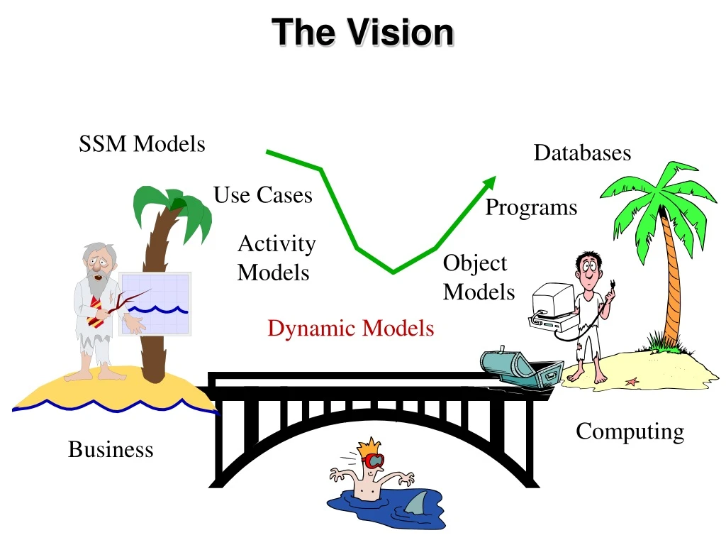
The Vision SSM Models Databases Use Cases Programs Activity Models Object Models Dynamic Models Computing Business
Beginnings of a Method Soft Systems Model
Types of Diagrams • Structural Diagrams – focus on static aspects of the software system • Class, Object, Component, Deployment • Behavioral Diagrams – focus on dynamic aspects of the software system • Use-case, Interaction, State Chart, Activity
Structural Diagrams • Class Diagram – set of classes and their relationships. Describes interface to the class (set of operations describing services) • Object Diagram – set of objects (class instances) and their relationships • Component Diagram – logical groupings of elements and their relationships • Deployment Diagram - set of computational resources (nodes) that host each component.
Behavioral Diagram • Use Case Diagram – high-level behaviors of the system, user goals, external entities: actors • Sequence Diagram – focus on time ordering of messages • Collaboration Diagram – focus on structural organization of objects and messages • State Chart Diagram – event driven state changes of system • Activity Diagram – flow of control between activities
Systems Activities • The systems functionality is represented as a number of Use Cases • The functionality of each use case will be realised through objects collaborating with each other • Collaboration is achieved through message passing
Message Connections • The arrow indicates that: • The sender sends a message • The receiver receives the message • The receiver takes some action, returning the result to the sender
Message Connections • The message must activate an operation in the receiving object
Message Connections There are two ways of knowing which object to send a message to: (1) An association exists between sender and receiver in the object model (2) The receiver’s object id is passed as part of the message (i.e. as a parameter)
Message Connections Sequence Diagramsallow us to describe object communication associated with a specific use case • Can be used: • during analysis to help define an object's responsibilities • as documentation for the final implemented software
Placing an Order • A message is sent to the order class to create a new “order” • Customer No., Stock items and Quantities are passed as parameters • Customer details are retrieved from the appropriate customer object • For each stock item an order line objectis created • Details are extracted from the stock item object
Library Example We have identified three objects: Borrower, Book and Librarian and the following relationship: Issuing a Loan Triggered by a request from a Borrower for the loan of a Book.
Library Example Before issuing the loan we need to check: 1) The borrower has no overdue fines 2) The borrower has not already reached the maximum number of loans that they are allowed. 3) None of the borrower’s current loans are overdue
Get Group Student Numbers Get Student Number
Get Module Results Get Student Marks
Exercise Each Instructor has a name, address and telephone number and is qualified to present one or more courses. We store the date when the instructor became qualified to teach the course A course has at least one instructor qualified to teach it but it may have many Each course has a number, title and a date of next revision Each course will have several scheduled presentations Details of the date, duration and location are recorded for each presentation Each presentation will be given by only one instructor but one instructor may give many presentations
The “Reschedule Presentation” use case • Sometimes a presentation needs to be rescheduled when this happens the availability of the existing instructor needs to be checked. If they are available they are assigned to the presentation on the new date. If not we need to release the current instructor, find all other qualified instructors and check their availability to identify a replacement.
Developing Sequence Diagrams • Identify the relevant objects involved in the computation • Establish the role of each object • Identify the controller • Identify the collaborators • Decide on the messages between objects
:Object 1 :Object 2 Actors Objects Sequence diagram notation
Sequence diagram notation :Object 1 :Object 2 Lifelines Identify the existence of the object over time.
Sequence diagram notation :Object 1 :Object 2 Activations Indicate when an object is performing an action
Sequence diagram notation :Object 1 :Object 2 message Messages Indicate the communications between objects
Sequence diagram notation :Object 1 :Object 2 message message Sequence Vertical position signifies sequence – earlier messages appear nearer the top.
Objects O1 O2 O3 O4 O5 indicates that the event effects the object E1 E2 Events E3 E4 Sequence Diagram • Tracks a sequence of events in a scenario • Identifies all objects involved
Sequence modelling For each event, ask “what objects does this involve?” • Used to identify new classes • Determines how classes interact
Use case elaboration • We define use cases as sequences - primary and alternative paths • Now we take sample sequences and build sequence diagrams • This gives us the objects • And it gives us the relationships • And it gives us the operations
The Primary Path The following sequence is carried out for every customer on the sales ledger who has not been billed in the last month: • Get sales items from the sales ledger. • Get customer details from the customer file, covering billing address details. • Get any credits that the customer has. • Get discount details for customer. • Print the invoice header • Print the line items on the invoice • Calculate any discounts • Apply any credits • Calculate and print the invoice total • Calculate and print the VAT • Mark items on sales ledger as invoiced
Now we can realise the use case • Elaborate the scenario with sequence diagrams • Find objects • Add operations to objects • Add attributes to objects
: Print Invoice Sequence diagram for Print Invoice usecase In recent years many OO gurus have suggested that we should introduce a control class for each Use Case. The control class drives the processing. For interactive use cases there is usually a boundary class too. We can put this object in a class diagram
Print Invoice Print Invoice - class diagram From our sequence diagram, we find our first object!
: Print Invoice : Customer Record Get Customer Name Now we implement the first step of the scenario by getting the Print Invoice control class to send a message. And then we need a recipient of the message. So we have found another object
Print Invoice Customer Record Print Invoice - class diagram We can see that as the objects communicate we need a relationship between them.
: Print Invoice : Customer : Invoice Record Get Customer Name Print Customer Name Moving on to the next step of the scenario We now have a third object!
: Print Invoice : Customer : Sales Items : Invoice Record Get Customer Name Print Customer Name Get Customer Address Print Customer Address Get Unbilled Invoicable Items Print Invoice Lines Print Total Print Terms and Conditions So we continue!
So what have we done? • Worked through a Use Case scenario step by step • Introduced a controller object to drive things • Sent messages from one object to another • Found objects to deal with the messages
What have we got left to do? • Find operations on objects to support the messages • Find attributes to support the objects
: Print Invoice : Customer : Sales Items : Invoice Record GetName( ) So we work through the messages and apply operations
: Print Invoice : Customer : Sales Items : Invoice Record GetName( ) PrintCustName( ) And so we continue
: Print Invoice : Customer : Sales Items : Invoice Record GetName( ) PrintCustName( ) GetAddress( ) PrintCustAddress( ) GetUnbilledItems( ) PrintLines( ) PrintTotal( ) PrintTermsConditions( ) And all the way through the sequence diagram
Working from a scenario Sending an email 1. Press “New ” email icon 2. Enter person’s name in “To” section 3. Type subject 4. Type contents 5. Press Send button 6. System looks up email address in address book 7. System submits the email to the email server
Starting the diagram • If this is an interactive scenario, we always have an actor driving it, so we put one on the sequence diagram
Add objects The first interaction is with the icon bar, which we can treat as an object
Add message The user talks to the icon bar