Radar measurements
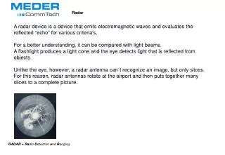
Radar measurements. FYS 3610. Radars. A radar transmit a radio pulse (pulse code), and receives the returned ”echo” sometime later. Radiowave propagation.

Radar measurements
E N D
Presentation Transcript
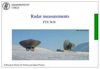
Radar measurements FYS 3610
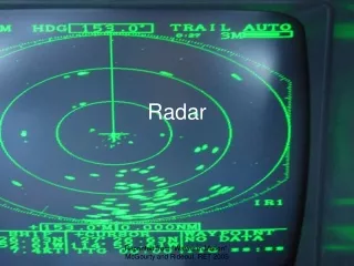
Radars A radar transmit a radio pulse (pulse code), and receives the returned ”echo” sometime later.
Radiowave propagation • It can be deduced that a radio signal is reflected in the ionosphere when it’s frequency f is equal to the local plasma frequency fp, where • To a good approximation, Hz , when ne is in [cm-3] • The peak electron density in the ionosphere is ~ 106 cm-3 (i.e. 1012 m-3). • This gives that fpe≤ 12 MHz
Inchoerent Scatter Radars (ISR) • The ISR uses frequencies well above the the plasma frequency in the atmosphere. • Typical frequencies used are from 50 MHz and up ( to 2 GHz). Such waves are almost unattenuated by the ionosphere, and pass through almost unaffected into space. • (Absorbtion is inversely proportional to the frequency of the signal, and has it’s maximum i the D-layer). • Therefore it is the small amount of energy scattered by the ionospheric electrons which is detected by the ISR method. • Since the scattered signal is very weak, very powerfull transmitters are used (PT ~ 106 W, PR ~ 10-15 W).
ISR – density measurements • The radio signal is transmitted in pulses. The range from the radar to the echoing region is determined by • The power in the returned signal is proportional to the density of electrons in the volume irradiated. This stems from the fact that each electron incoherently radiates back a small amount of the incident energy. The electric field in the transmitted wave causes the electrons encountered by the radar pulse to oscillate, resulting in radiaton of a signal at almost the same frequency (Thomson scattering).
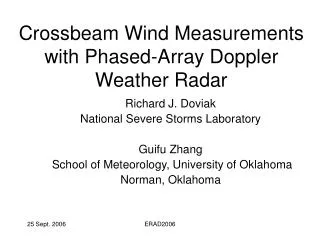
ISR – velocity measurements • The electrons are in thermal motion, and hence the backscattered signal is Doppler shifted from the incident frequency. This gives information about the radar line of sight velocities of the scattering electrons. • As long as the neutral density is much larger than the electron density (low ionisation), the electrons will follow the movements in the neutral gass, and the radar measurements can be used for studying the dynamics in the atmosphere.
ISR – Doppler spectrum due to scattering from thermal fluctuations in the ion line • Number density ~ power/area under the curve. • The width Δf determines the ion temperature. • Te is determined from the intensity of the ”wings”/shoulders in the spectrum. • The frequency shift fo from the transmitt frequency fT gives the mean ion velocity.
ISR – Doppler spectrum explanation An incoherent scatter radar echo comes from a very large number of electrons. These are not stationary, but rather in random thermal motion. Thus the echo will not be at a single frequency, but a range or spectrum of frequencies near the transmitter frequency. As the temperature increases, the average velocity of the electrons increases, and the range of velocities increases. Put another way, the width of the spectrum increases. The width of the spectrum is then a measure of the temperature of the ionosphere, and the incoherent scatter radar functions as a thermometer. In fact, there are two temperatures in the ionosphere. When an electron is removed from an atom, the remaining atom, which is now missing an electron, is known as an ion. The ion gas may have a different temperature from the electron gas. As a result of electrical interactions between the ions and electrons, the width of the spectrum measures the ion temperature. However, the spectrum usually has two peaks, or wings/shoulders, and the height of these shoulders measures the electron temperature. The electron/ion mixture is known as a plasma, and in addition to the thermal motions, the entire plasma is usually in motion. In other words, there is a plasma wind. As a result, the entire spectrum will be shifted instead of being centered on the transmitter frequency. Thus an incoherent scatter radar also functions as a wind speed meter.
EISCAT Scientific Association Three Incoherent Scatter Radar Systems: Tromsø VHF (224 MHz) Tromsø UHF (933 MHz) EISCAT Svalbard Radar (500 MHz) - dual antenna system Associated countries:Germany, France, Finland, Japan, Norway, Sweden, UK
Coherent Scatter radar • In the troposphere and stratosphere changes in the index of refraction is mainly attributed to changes in temperature and the content of water vapor. • In the ionosphere the density of free electrons determine the index of refraction. • The radio signals are scattered from irregularities or gradients in the atmospheres index of refraction (n). • n = c / v c = velocity in vacuum, v = velocity in the medium
Coherent radar– backscatter targets • The scattering wavelength is one half the transmitted wavelength, meaning that backscatter occures when the irregularities have a size of approximately on half the radar wavelength (constructive interferense). • Example: A medium frequency radar operating at 10 MHz . This gives a wavelength of This means that this radar will give backscatter when the irregularities are in the size of ~ 15 meters.
SuperDARN Radars A network of HF radars that monitors the high-latitude ionosphere.
Radar Beam • As pulses travel away from the antenna; the beam takes on a cone-like appearance and expands in all directions. • This expansion or beam broadening increases pulse volume. Beam width (opening angle) : Where k is a numeric factor (k ~ 1) and D is the antenna aperture.
Radar Beam • While the amount of power within a pulse is determined by its length and remains constant, power density decreases with distance. This occurs because the pulse’s fixed amount of energy is spread over a greater area (pulse volume) as the beam broadens. • The further a pulse travels, the weaker and less effective it becomes due to increased pulse volume. • Radars with small beam widths are necessary to provide good target resolution. • Hight resolution / spatial resolution of a radar depend on the height of the backscatter targets !