Download
1 / 12
120 likes | 166 Vues
Explore the new High-Speed Signal Processing (HSSP) project aiming to enhance aircraft radar capabilities through cutting-edge technology. Research includes real-time programming, radar applications, computer architecture, and more. Join us in shaping the future of air combat awareness.

E N D
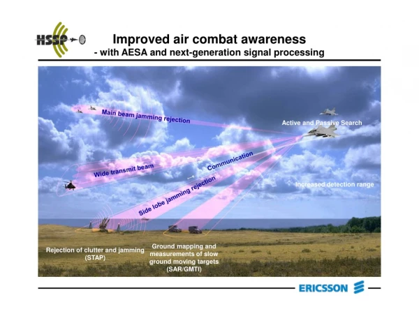
Improved air combat awareness- with AESA and next-generation signal processing Main beam jamming rejection Active and Passive Search Communication Wide transmit beam Increased detection range Side lobe jamming rejection Ground mapping and measurements of slow ground moving targets (SAR/GMTI) Rejection of clutter and jamming (STAP)
The challenge • The AESA performance should fit in the same“box” as today’s systems, considering • Physical size • Power dissipation • Physical robustness • The High Speed Signal Processing(HSSP) project • A joint project between Ericsson Microwave Systemsand Halmstad University, Sweden • The goal of HSSP: “1 TFLOPS in a shoe box”
Real-time programming Modeling Radar applications & algorithms Building techniques Computer architecture Algorithm parallelization Communication High Speed Signal Processing project • Research for the FUTURE • Embedded high speed signal processing computer systems for the next generation fighter aircraft radar. • Our GOALS • Strengthen our competence to ensure realization in the future • Find engineer efficient and economic solutions • Actively cooperate in a wide competence network Software development environment
System realization • Realizable with 0.13 mm technology (LSI Logic G13) • The system is based on in-house SIMD based ASICs (the compute engines) • The modules are interconnected in a ring topology by a high speed communication network (GLVDS) • The system scales to >1 TFLOPS • A multi-module system concept • SIMD compute engines for high performance • MIMD on system level for flexibility • Identical compute engines
CU GLVDS PCI GLVDS Flex-foil PCI-PCI bridge IOC M ASIC node ASIC node M M ASIC node ASIC node M HSSP system HSSP-system (Opto) data in -> data out -> 64 <- ctrl 1 TFlops 32 Register File 3 FPU 64 32 CP-bus 32 Serial Mask Register AMU CUIM 64 64 CP-bus GLVDS 64 CNW 64 HSNW CUDM CP-bus UART PE HWsync COMU Tim.WD 2 Flash PEDM PA-bus Boot 64 CP-bus IRQ 31 Processing element IM PCI 32 MP DM 400 MFlops PA-bus Memory Processing array PA2 PA1 13 GFlops ASIC node 25 GFlops HSSP-card MIMD SIMD 200 GFlops
HSSPCard HSSP system BE • Five HSSP cards (cassettes) • High speed ring network • Utility bus • Front end (FE) with opto-interface • Back-end (BE) with utility bus interface • Performance: >1 TFLOPS FE (Opto) data in -> data out -> <- ctrl MIMD
HSSP card (cassette) GLVDS PCI GLVDS • 8 ASIC nodes per board, 4 on each side • Double direction GLVDS ring network with separate data (1.6 GB/s) and control channel (100 MB/s) • Utility bus • DRAM • Performance: 200 GFLOPS Flex-foil PCI-PCI bridge M ASIC node ASIC node M M ASIC node ASIC node M MIMD
IOC ASIC node Serial • Two processor arrays, acting as co-processors • Master processor, IP-core running a commercial RTOS • I/O-processor (DMA, data transformations, etc.) • Support functions (Boot, UART, Timer, etc.) • 0.13mm technology minimum • Performance: 25 GFLOPS GLVDS CNW HSNW UART HWsync Tim.WD Flash Boot CP-bus IRQ IM PCI MP DM PA-bus Memory PA2 PA1 MIMD
CP-bus CP-bus CUIM CU CUDM CP-bus PE 2 PA-bus PEDM 31 32 Processor array (PA) • 32 processor elements, 400 MHz, ring topology • 32 kB memory per element • Custom control unit w/ memory • Performance: 12.5 GFLOPS SIMD
64 32 Register File 3 64 FPU 32 32 AMU Mask Register 64 64 64 64 COMU 64 Processor element (PE) • 64 32-bit registers, 4 read and 3 write ports • 4 stage pipelined FPU, IEEE 754 • fmul, fadd, fsub, mask operations • North/South communication interface • 64 bit memory access, skewed load and store, 3.2 GB/s BW • Performance: 400 MFLOPS SIMD
Runtime environment • Commercial RTOS based • Custom libraries • Layered architecture DSP application Communication Library Algorithmic Library Custom runtime routines Real Time Operating System • In house development • Commercial RTOS/IDE • Hardware Driver routines Driver routines Hardware HSSP system Single processor simulator MIMD
VLSI test implementation • One processor array • Clock and control distribution • LSI Logics G12 process (0.18 mm), standard cell • Total area 227 mm2 • Clearly dominated by memories • Memory size can however be substantially decreased • Control unit and processor elements capable of 335 and 396 MHz, respective • Top level design capable of 210 MHz • Control distribution a bottle neck, can however be pipelined


![[Unix Programming] Signal and Signal Processing](https://cdn3.slideserve.com/5708599/unix-programming-signal-and-signal-processing-dt.jpg)