Download

1 / 37
370 likes | 503 Vues
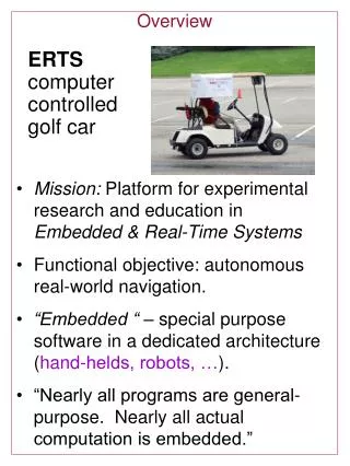
This project showcases a state-of-the-art remote-controlled car that utilizes a wireless link (75.870 MHz) from a host computer, featuring an on-board camera (2.4 GHz) with an amplifier for extended range. It includes user-friendly software for remote operation, supporting applications like home surveillance, maneuvering in small spaces, and even espionage missions. The system allows operation up to 100 feet with minimal delay and can be adapted for RC boats, planes, or helicopters, making it a versatile tool for various uses.

E N D
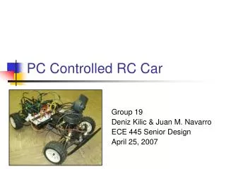
PC Controlled RC Car Team #12 Sunil Kondala Orbay Tuncay Kyle Zars
Features • Wireless Link (75.870 MHz) from Host Computer to Car • On-board Wireless Camera (2.4GHz) with Amplifier for Extended Range • User-Friendly Software Control Interface • Remote Login Capability
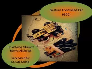
Possible Uses • Visual security for entire home with one unit • Maneuver and see into small spaces • Espionage missions • Can also be implemented on an RC boat, plane or helicopter
Objectives/Goals • Make Car Operational Up to 100 ft. (With No Obstacles) • Success – Also Operates Up to 58 ft. Through Two Brick Walls • Delay Between Video Frames on Remote Computer Less than 500 ms. • Success • Delay Less than 100 ms for LAN Connection (MS Remote Desktop)
Design Overview Host PC Remote Control Circuitry/Transmitter Breakout Board Digital Potentiometers Receiver Remote PC Amplifier Camera Receiver/Car
Used for RC Cars, Boats, Airplanes Operates at: 12V, 150mA Utilizes Amplitude Modulation (AM) 26.995MHz to 75.990MHz Channel BW=10kHz Operates at 75.870MHz Channel: 84 XR2i Remote Control
Interior Components • Mechanical Potentiometers • Microprocessor • RF transmitter board • Telescopic Antenna
This potentiometer sweeps through resistances from as low as 60 Ω to as high as 5 kΩ W-> (pin 18 and pin 15) Varies Voltage from 0.8V to 3.8V Potentiometer Mechanical Potentiometer
Microprocessor • Pin 18 (throttle) -> Pin 43 of microprocessor Pin 15 (steering) -> Pin 42 of microprocessor • The ADC in the microprocessor
Digital Potentiometers • 10 KΩ potentiometer • Operates from 2.7V to 5.5V • Current through wiper = 0.12μA Maxim DS1866
Digital Potentiometers • PIN DESCRIPTION H – High End terminal L – Low End terminal W – Wiper Arm P0 – LSB data input P1 – Bit 1 data input P2 – MSB data input Pin 4 – Ground Pin 8 - VCC
Software Interface Design • Buttons vs. Scrollbars or Keyboard • Parts Decision • Digital Potentiometers – Maxim Part #DS1866 • 3 Parallel Inputs (data bus on parallel port is 8 bits) • Operates at 5V (same as parallel port signal voltage) • Output Current Same as Mechanical Pots (~1-2 µA) • 10 kΩ Variable Resistance Range • Parallel Cable Breakout Board • Cost • Easy Terminal Strip/Screw Interface
Software Algorithm Overview • Click on Button – takes you to function • #define Data 0x378 • int Bits; • Conditional Statements on Bits • Holds one channel constant while changing the other • Set Bits to new value • _outp(Data,Bits)
Issues Accessing Parallel Port • Windows XP does not allow access by default • Found UserPort software (shareware) • Configures the Behavior of the Driver
Video Transmitting Software • Clipstream Live (shareware) • Compresses Video to Transmit Over IE • Also Conveniently Compresses Enough For MS Remote Desktop
Capture Card • ATI TV Wonder Card • Receives Coax Input From Wireless Camera Receiver • Clipstream Software Uses this Card for Input of Video Signal
X-10 2.4GHz Wireless Camera Operates w/12V DC, 80mA Resolution : 310 TV lines RF Output of 50,000uV/m @3m FM modulation Receiver operates at 4 channels 2.411GHz to 2.473GHz Channel BW is 18MHz Transmission Range 100ft ANS-900 2.4GHz Monopole 50Ω input impedance 2.5dbi omni-directional gain 1.5:1 VSWR max 10W max input power What we have?
How much amplification do we need? Amplification= Free Space Loss + Path Loss Friis Transmission Formula: PR = PT DT DRλ2 16 π2 d2 PR=Power received by receiving antenna PT=Power radiated by transmitting antenna DT = Directivity of the transmitting antenna DR = Directivity of the receiving antenna λ = Wave length d = Separation between antennas
Free Space Loss: Using Friis Transmission Formula: • Since PT DT DRλ in Friis Formula doesn’t change for different separations, power received is inversely proportional to separation squared: Power Ratio = PR(55ft) = (100ft)2 PR(100ft) (55ft)2 Free Space Loss = 10 log (Power Ratio) [dB] = 5.193dB
Path loss can be estimated as 5dB/wall Typical 2 bedroom apartment has 3 walls Path Loss: http://www.genisysnetworks.com http://www.imperialsouth.com/2bedroomfloorplan.html Path Loss = 5dB/wall * 3 walls = 15 dB Amplification needed = 20.193 dB
X10 transmitter output Spectrum of video signal (20MHz BW) Power spectrum of the transmitter output Output power of the transmitter at 2.411GHz (channel A) = 3.883dBm
Specifications of final power amp: Operate at 2.4GHz ISM band ≈21dB gain High efficiency i.e. low voltage operation Low input power i.e. 4dBm Max output power of 1W≈30dBm (limited by FCC) Impedance matched to 50Ω Desired power amp RF2163 1800MHz to 2500MH operation range Operation voltage 3.3V 19dB gain w/Pin=10dBm +30dBm saturated output power Impedance matched to 50 Ω w/impedance matching network Amplification at the output of transmitter
Output power of transmitter w/MAR8 and 10dB attenuator GMAR8(2.4GHz) = = Pout + 10dB – PTx = 3.47dBm + 10dB – 3.883dBm = 9.587dB OR Wireless camera range of 100ft in free space and ≈1 dry wall BW doesn’t change information is preserved therefore can be substituted for RF2163 Using what we have: MAR8
Overview of MAR8 Vcc = 12V, I = 40mA Powered by RS51-0124 battery
Characterization of MAR8: Input/Output Missmatch • Matched to 50Ω at the input: |S11|< -15dB 2.32GHz < f < 2.48GHz • Matched to 50Ω at the output: |S22|<-15dB 2.33GHz < f < 2.45GHz
Characterization: Stability • Unconditional Stability Criteria are satisfied: • K > 1 2.22GHz < f < 2.60GHz • B1 > 0 0 < f < 2.60GHz
|S21|=12dB f = 2.40GHz Measured gain=9.5dB Since we are operating at power levels 4 dBm, cable losses are significant and effect the measured gain. Characterization: Gain
Challenges/Problems • Operation of Potentiometers • Trouble Figuring Out Correct Configuration • Added 1 kΩ Resistors in Series Between Parallel Port and Input Pins • Amplifier • Was Not Feasible to Build One Given the Time Constraint • Non-Functional Substitutes • Initialization of RF Signals Being Transmitted When Car Is Powered on
Thanks To: • Professor Swenson • Derek Gottlieb • Professor Steven J. Franke • Professor Alex Cangellaris • Chad Carlson • Josh Potts