Download
1 / 12
140 likes | 416 Vues
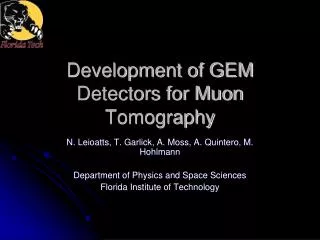
Development of GEM Detectors for Muon Tomography. N. Leioatts , T. Garlick , A. Moss, A. Quintero, M. Hohlmann Department of Physics and Space Sciences Florida Institute of Technology. Gas Electron Multiplier (GEM). Particle detector technique (1).

E N D
Development of GEM Detectors for Muon Tomography N. Leioatts, T. Garlick, A. Moss, A. Quintero, M. Hohlmann Department of Physics and Space Sciences Florida Institute of Technology
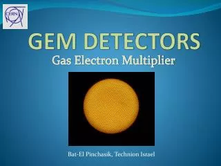
Gas Electron Multiplier (GEM) • Particle detector technique (1). • Constructed of Kapton foil clad in copper on both sides, with holes through layers (1). • Voltage applied • High electric field in holes • Avalanche of ions and e- • e- collected (2). (1) Sauli, F.; NIM A386 531, 1997. (2) http://cerncourier.com/cws/article/cern/27921
Our GEM • Triple GEM • Limit to Gain per foil (sparking) • 4 foils made • Planned Use: Homeland Security (Muon Tomography for detection of nuclear contraband. J. Helsby, et al. FAS 2008) • 70:30 Ar:CO2 • 55Fe Source for testing • Emits monoenergetic 5.9 KeV X-ray
Our Detector • HV circuit • Readout Amplifier • Oscilloscope
Construction • Arrive • Stretched • On Machined G10 Frames • Mounted • With Stycast • Cut • Assembled • On lid of detector
Then It Works!! • Not so much • Large leakage current • Peak occurs much lower than GEM operating voltage (3) (3) F. Murtas. LNF-INFN. Frascati (2002)
Areas that Needed Improvement • GEMs Sparking • Box Pressure • Gluing • Larger Clamps • Amplifier Readout
Improvements • Gas Leakage • Sturdier Steel Frames • 8” C-clamps • Stycast • Soldered connector pins • Amplifiers • Characterized • differential to single side amplification Amplifier B, Tested with a Square input
Electric Field Testing • Linear Output from HV circuit • Operating Voltage: • Vin ~ 9V • Produces 300V across a single foil
Individual Testing • Motivation: High leakage current between foils • Systematic testing of each foil (4) • Current drops with time • As in a capacitor • Foil I shows a larger leakage current than Foils III and IV (4) Barbeau, P.S. et al. NIM A 515 (2003)
Conclusions • Solved physical (gas) leakage problems • Still has electrical (current) leakage problems • Currently working on this
Future • Continue individual testing until all foils are satisfactorily characterized • Reinstall Detector and continue to troubleshoot problems until detector works satisfactorily • Move to the construction of a larger detector