ROBOX modification plans
ROBOX modification plans. HF ECR follow up Nov 29,2010. Ianos Schmidt. Design plan. Slice test box. Sleeve material selection. Optical/mechanical mock up Test light guide coupling Test sleeve performance Test PMT shielding, support, grounding, noise…. Define cabling interfaces.

ROBOX modification plans
E N D
Presentation Transcript
ROBOX modification plans HF ECR follow up Nov 29,2010 Ianos Schmidt
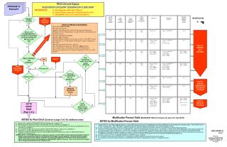
Design plan Slice test box Sleeve material selection • Optical/mechanical mock up • Test light guide coupling • Test sleeve performance • Test PMT shielding, support, grounding, noise… Define cabling interfaces • Validate/update CAD of box components • Produce a new plate 2 Plate 3 design Sleeve/optical Coupling design Produce proto plate 3 Try 2? Design parts for PPP Try 2? PPP • Testing • Electrical • optical • Test beam? • Magnet field test Plate 2 decision Modify / produce from scratch Make from scratch P5 modification/assembly Produce parts Installation / commissioning
Slice test readout box Replaces eight lowest eta PMT’s with Hamamatsu R7600U-200-M4 PMT’s Existing “plate 2” Existing PMT shields For 16 standard HF PMT’s Base board for new PMT’s: • Conventional resistive bases • provides“Reference” signals for QIE • Ground connections to shields • Safety ground “Mini Plate 2” New PMT shields
Slice box assembly cross-section for R7600U PMT’s Shield Ground strap Base board Plate II PMT Kapton insulator “Iron” shield ~17mm PMT to light guide Optical coupling (“sleeve”) Plate I Light guide mirror Light guide assembly (part of wedge)
Box tested in BAT904 • Test setup: • Slice box • HF front end crate + Calibration Unit • HF LASER/LED light distribution fibers and CLI • HF front end cables • HF HV supply + CAEN supply • HV adapter cable, later installed in USC • TESTS: • Laser/LED • Channel mapping verification • HV mapping • Gain/single PE • CAEN HV supply test • HV cable adapter test • Pedestal and light tightness HF ROB test unit Simulates calibration light distribution of HF wedge * Big thanks to Halil Saka for his work in 904
Location of new PMT’s IPHI 67 Covered PMT (IETA 29, short) New PMT’s are located on HF+ at IPHI 67 and cover towers IETA 29 to IETA 32
HF+ IPHI 3 light guide mirrors replaced AFTER BEFORE
Sleeves in IPHI 3, IETA 29 “Telescopic” Sleeve made of 3M radiant mirror film (“HEM”). Non conductive. TEFLON IETA 29S Mirror Light guide tube TYVEK IETA 29L In HF+ IPHI 3 all mirrors were replaced with standard “German Mylar”. HEM sleeves were installed everywhere except IETA 29S and IETA 29L which have Teflon and Tyvec sleeves respectively.
Single PMT mock up. Mechanically and Optically identical to a single channel of a HF ROB. For study of PMT insulation, support, shielding, electrical and optical coupling. Ianos Schmidt. Oct. 11,2010
Single PMT mock up • Three sets of components were produced. • One for Iowa lab for sleeve design and testing • One for Mechanical design evaluation • One for testing at CERN (Sources, testbeam …) HF “backplane” Plate 1 Plate 2 Shield Light guide Mirror & sleeve
Box design • Design of new box components started. Initial pass on mechanical features effecting base board design was provided to Sergey for prototype production. • Some concerns about the strength of grade XX Garolite for plate 2’s. • - No longet entertain possibility to modify existing plate 2’s.
Work space estimates at CERN Box assembly area ~12m^2 (P5) Box test area ~12m^2 (P5) Box storage area ~5m^2 (P5) Cable prep area ~14m^2 (at CERN) Cable storage ~5m^2 (P5) Workspace needed at P5 24m^2 Storage at needed at P5 10m^2 Cable prep area (CERN) 14m^2 TOTAL 48m^2