
Evaluation of Burnthrough Resistance Test Method for Insulation Materials
E N D
Presentation Transcript
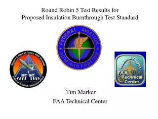
Discussion of Test Method to Determine the Burnthrough Resistance of Thermal/Acoustic Insulation Materials Tim Marker FAA Technical Center
INTERNATIONAL AIRCRAFT MATERIALS FIRE TEST WORKING GROUP MEETING Held at Airbus Industries, Hamburg, Germany June 23-24, 2003 TUESDAY, JUNE 24, 2003 Task Group Meetings Burnthrough – Noel Spurlock (Boeing) presented Boeing’s Thermal Acoustic Insulation Material Burnthrough Test Procedure. This will be sent to Tim Marker for review/comments, etc., and then sent out to the labs to set their test equipment up. Once labs are set up to these specs, a Round Robin will be conducted on two materials, and then Tim or someone from the FAA Technical Center will visit each lab to ensure all labs have their test apparatus set up the same. Jim Davis and Noel Spurlock will jointly research the creation of a “new” airflow meter (?) and send their findings to FAATC for review and prepare a presentation for the fall 2003 Materials Meeting. Advisory Material: Randy Smith will put together a list of odd areas in the airplane and Boeing’s proposed methods for complying with the proposed Rule and send it to Tim Marker to review and to possibly be added to the advisory material as soon as possible. Randy will talk to Peter Busch of Airbus to try to collaborate this project with Airbus.
INTERNATIONAL AIRCRAFT MATERIALS FIRE TEST WORKING GROUP MEETING Held at Airbus Industries, Hamburg, Germany June 23-24, 2003 TUESDAY, JUNE 24, 2003 Task Group Summaries Burnthrough Task Group (Dick Hill): Boeing presented its Thermal Acoustic Insulation test procedure. Tim Marker will review this information. If he agrees with it, this information will be sent to each participating lab and a Round Robin will be conducted on a couple of materials with a representative from the FAA Technical Center present during each set of tests to ensure every lab sets up and conducts the tests in the same manner.
INTERNATIONAL AIRCRAFT MATERIALS FIRE TEST WORKING GROUP MEETING November 19-20, 2003 Hosted by Boeing Commercial Airplane Group, Seattle, Washington, USA THURSDAY, NOVEMBER 20, 2003 Task Group Reports Burnthrough Task Group Report – R. Hill A number of topics were addressed. The definition of ‘halfway’ as written in the rule was discussed. A presentation was given on alternate definitions that were thought to be similar to the one in the rule. The FAATC will discuss these other interpretations of the rule with the FAA regulatory side. The FAATC will try to address some of the issues brought up during this Task Group meeting under “Burnthrough” on its website as updates, etc., once these issues are discussed with the regulatory side.
FAATC Review of Thermal Acoustic Insulation Material Burnthrough Test Procedure
THERMAL ACOUSTICINSULATION MATERIALBURNTHROUGHTEST PROCEDURE NOEL L SPURLOCK BOEING COMMERCIAL AIRPLANES AERO / NOISE / PROPULSION LABORATORY SEATTLE, WASHINGTON
THERMAL ACOUSTIC INSULATION MATERIAL BURNTHROUGH TEST PROCEDURE 1 Verify burner assembly – Park Model DPL 1.1 Components 1.1.1 Blower – 5.25” diameter X 3.50” deep 1 1.1.2 Fuel nozzle – Monarch, 6.0 GPM, 80o, PL 1 ( PL - hollow cone or PLP - semi-hollow NO! ) 1.1.3 Stator – Monarch H215, CCW, 4” diameter 1 1.1.4 Turbulator – Monarch F124, CCW, 4 X 23/4 1( 4.00” diameter 3/4OD X 2.75” diameter ID ) 1.1.5 Burner cone – 6” H X 11” W ( R3.0 )X 12” L ( All dimensions ± .125”2) X
Part VII – Test Method to Determine the Burnthrough Resistance of Thermal/Acoustic Insulation Materials b. Apparatus (1) Test Burner. The arrangement of the test apparatus is shown in figures 1 and 2 and must include the capability of swinging the burner away from the test specimen during warm-up. (2) Test Burner. Must be a modified gun-type such as the Park Model DPL 3400. flame characteristics are highly dependent on actual burner set-up. Parameters such as fuel pressure, nozzle depth, stator position, and intake airflow must be properly adjusted to achieve the correct flame output. (i) Nozzle. A nozzle must maintain the fuel pressure to yield a nominal 6.0 gal/hr (0.378 L/min) fuel flow. A Monarch-manufactured 80o PL (hollow cone) nozzle nominally rated at 6.0 gal/hr at 100 lb/in2 (0.71 MPa) delivers a proper spray pattern. (ii) Fuel Rail. The fuel rail must be adjusted to position the fuel nozzle at a depth of 0.3125 inch (8 mm) from the end plane of the exit stator, which must be mounted in the end of the draft tube.
THERMAL ACOUSTIC INSULATION MATERIAL BURNTHROUGH TEST PROCEDURE 1 Verify burner assembly – Park Model DPL 1.2 Configuration 1.2.5 Draft tube to cone exit plane – 12.0” 2 1.2.6 Draft tube angle – 30o3 ( from horizontal ) 1.3 Operation 1.3.1 Fuel flow = 6 ± 0.2 GPM 1 1.3.2 Fuel pressure = 100 psig 1.3.3 Air flow = 2150 ± 50 ft/min 1 (adjust with blower and hose-end dampers NO!- see 2.4 )
Part VII – Test Method to Determine the Burnthrough Resistance of Thermal/Acoustic Insulation Materials b. Apparatus (3) Calibration Rig and Equipment (con’t) (v) Air Velocity Meter. Use a vane-type air velocity meter to calibrate the velocity of air entering the burner. An Omega Engineering Model HH30A is satisfactory. Use a suitable adapter to attach the measuring device to the inlet side of the burner to prevent air from entering the burner other than through the measuring device, which would produce erroneously low readings. Use a flexible duct, measuring 4 inches wide (102 mm) by 20 feet (6.1 meters) long, to supply fresh air to the burner intake, to prevent damage to the air velocity meter from ingested soot. An optional airbox permanently mounted to the burner intake area can effectively house the air velocity meter and provide a mounting port for the flexible intake duct.
THERMAL ACOUSTIC INSULATION MATERIAL BURNTHROUGH TEST PROCEDURE 2 Adjust test Apparatus 2.1 Thermocouple rake 2.1.1 Thermocouples – seven 1/8”, grounded, type K, metal sheathed 3 24 AWG, Ceramic Packed 2.1.2 Rake configuration ● 30o from vertical ● 1” between T/C w/ 3” exposure to flame 3 2.1.3 Rake position ●T/C tips 1” above cone horizontal CL ● Middle T/C on cone vertical center line ● T/C plane 4” from cone exit plane 3
Part VII – Test Method to Determine the Burnthrough Resistance of Thermal/Acoustic Insulation Materials b. Apparatus (3) Calibration Rig and Equipment (con’t) (iii) Calorimeter Mounting. Mount the calorimeter in a 6- by 12- +0.125 inch (152- by 305- +3 mm) by 0.75 +0.125 inch (19 mm +3 mm) thick insulating block which is attached to the heat flux calibration rig during calibration (figure 4). Monitor the insulating block for deterioration and replace it when necessary. Adjust the mounting as necessary to ensure that the calorimeter face is parallel to the exit plane of the test burner cone. (iv) Thermocouples. Provide seven 1/8-inch (3.2 mm) ceramic packed, metal sheathed, type K (Chromel-Alumel), grounded junction thermocouples with a nominal 24 American Wire Gauge (AWG) size conductor for calibration. Attach the thermocouples to a steel angle bracket to form a thermocouple rake for placement in the calibration rig during burner calibration (figure 5).
THERMAL ACOUSTIC INSULATION MATERIAL BURNTHROUGH TEST PROCEDURE 2 Adjust test Apparatus 2.4 Burner air flow ●Hose-end damper set to 50% NO! ●Blower damper set to 2150 ± 50 ft/min 1 2.5 Vent Hood 2.5.1 Vertical air flow = 100 ± 50 ft/min 5 2.5.2 Horizontal air flow < 50 ft/min 5 2.6 Calorimeter cooling water 2.6.1 Water temperature = 120o F( 48.8o C ) 2.6.2 Water flow rate > 1 GPM
THERMAL ACOUSTIC INSULATION MATERIAL BURNTHROUGH TEST PROCEDURE 4 Calibrate Burner 4.1 Two minute warm-up 4.2 Thermocouple rake 3.2.1 Thirty seconds to stabilize NO! 3.2.2 Record data for thirty seconds 4.3 Calorimeter 3.3.1 Thirty seconds to stabilize NO! 3.3.2 Record data for thirty seconds 4.4 Examine data – burner adjustments if required
Part VII – Test Method to Determine the Burnthrough Resistance of Thermal/Acoustic Insulation Materials e. Calibration (5) Warm-up and Temperature Check Position the burner in front of the thermocouple rake. After checking for proper alignment, rotate the burner to the warm-up position, turn on the blower/motor, igniters and fuel flow, and light the burner. Allow it to warm up for a period of 2 minutes. Move the burner into the calibration position and allow 1 minute for thermocouple stabilization, then record the temperature of each of the 7 thermo- couples once every second for a period of 30 seconds. Turn off burner, rotate out of position, and allow to cool. Calculate the average temperature of each thermocouple over this 30- second period and record. The average temperature of each of the 7 thermocouples should be 1900oF + 100oF (1038 + 56oC).
Part VII – Test Method to Determine the Burnthrough Resistance of Thermal/Acoustic Insulation Materials e. Calibration (4) Warm-up and Heat Flux Check While the burner is still rotated to the warm-up position, turn on the blower/motor, igniters and fuel flow, and light the burner. Allow it to warm up for a period of 2 minutes. Move the burner into the calibration position and allow 1 minute for calorimeter stabilization, then record the heat flux once every second for a period of 30 seconds. Turn off burner, rotate out of position, and allow to cool. Calculate the average heat flux over this 30-second duration. The average heat flux should be 16.0 +0.8 Btu/ft2 sec (18.2 +0.9 W/cm2).
Nov 1999 Date: 11/24/99
2 ADJUST TEST APPARATUS 2.4 Burner Air Flow Adjustment and Verification Set hose-end damper to 50% NO! Set burner damper to 2150 ft/min Monitor air flow with an Omega HH-30 air velocity meter
4 CALIBRATE BURNER 4.1 Two Minute Warm-up (position 1): Allow burner to stabilize – check air flow 4.2 Move burner to T/C rake (position 2): Stabilize 30 seconds – record data 30 seconds 4.3 Move burner to calorimeter (position 3): NO! COOL Stabilize 30 seconds – record data 30 seconds Burner Position 1 Burner Position 2 Burner Position 3
Part VII – Test Method to Determine the Burnthrough Resistance of Thermal/Acoustic Insulation Materials e. Calibration (4) Warm-up and Heat Flux Check While the burner is still rotated to the warm-up position, turn on the blower/motor, igniters and fuel flow, and light the burner. Allow it to warm up for a period of 2 minutes. Move the burner into the calibration position and allow 1 minute for calorimeter stabilization, then record the heat flux once every second for a period of 30 seconds. Turn off burner, rotate out of position, and allow to cool. Calculate the average heat flux over this 30-second duration. The average heat flux should be 16.0 +0.8 Btu/ft2 sec (18.2 +0.9 W/cm2).
Part VII – Test Method to Determine the Burnthrough Resistance of Thermal/Acoustic Insulation Materials e. Calibration (5) Warm-up and temperature Check Position the burner in front of the thermocouple rake. After checking for proper alignment, rotate the burner to the warm-up position, turn on the blower/motor, igniters and fuel flow, and light the burner. Allow it to warm up for a period of 2 minutes. Move the burner into the calibration position and allow 1 minute for thermocouple stabilization, then record the temperature of each of the 7 thermo- couples once every second for a period of 30 seconds. Turn off burner, rotate out of position, and allow to cool. Calculate the average temperature of each thermocouple over this 30- second period and record. The average temperature of each of the 7 thermocouples should be 1900oF + 100oF (1038 + 56oC).
5 PREPARE TEST SPECIMEN 5.2 Mount Test Specimen in Holder • Flat against stringers • Tuck into frame/stringer corner • Clip to frame picture shows OEM clips, not 1” by 2” clips
Part VII – Test Method to Determine the Burnthrough Resistance of Thermal/Acoustic Insulation Materials c. Test Specimens (3) Construction (con’t) (iv) Installation on Test Frame. Attach the blanket test specimens to the test frame using 12 steel spring-type clamps as shown in figure 7. Use the clamps to hold the blankets in place in both of the outer vertical formers, as well as the center vertical former (4 clamps per former). The clamp surfaces should measure 1 inch by 2 inches (25 by 51 mm). Place the top and bottom clamps 6 inches (15.2 cm) from the top and bottom of the test frame, respectively. Place the middle clamps 8 inches (20.3 cm) from the top and bottom clamps. (Note: For blanket materials that cannot be installed in accordance with figure 7, the blankets must be installed in a manner approved by the FAA.)
Discussion of Test Method to Determine the Burnthrough Resistance of Thermal/Acoustic Insulation Materials Installation of Test Samples on Test Frame
Round Robin VI Testing Sequence Initial Calibration A1, B1, C1, B2, C2, A2, C3, A3 Second Calibration B3, A4, B4, C4, B5, C5, A5, C6 Third Calibration A6, B6, A7, B7, C7, B8, C8, A8
Round Robin VI Tasks Completion of all test samples needed Refine test spreadsheet Update Calibration Guidelines document FAATC witnessing of burnthrough testing using RRVI samples Use Boeing-manufactured calibration tools to check labs