Plasma Instrument Calibration System for Space Missions
180 likes | 304 Vues
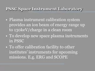
A plasma instrument calibration system providing ion beams up to 130keV/charge in a clean room for PSSC's space plasma instruments and other institutes' upcoming missions. The system measures energy range, incident angle, and beam area to develop new instruments.

Plasma Instrument Calibration System for Space Missions
E N D
Presentation Transcript
PSSC Space Instrument Laboratory • Plasma instrument calibration system provides an ion beam of energy range up to 130keV/charge in a clean room • To develop new space plasma instruments in PSSC • To offer calibration facility to other institutes’ instruments for upcoming missions. E.g. ERG and SCOPE
Overview To obtain the relationship between count rate and particle distribution function, the instrument response to known beam energy and incident angle is measured beam area (>50 cm2), energy range (~130 keV)
Ion source Electron gun • Ionization of neutral gas by electron impact • Ions are collimated and accelerated (~10keV) by electrostatic lenses. Ion trajectory simulation Blue line: Ion trajectory, mass=1, Red, green line: Potential contour Ring electrodes: 8000V ~ 0
+V B -V Mass spectrometer Ion trajectory simulation Green line: Mass 32, Blue line: Mass 28 V=+/-21 V, B=0.3T, Initial acceleration: 3kV • Mass separation is done by a crossed electric field and magnetic field (ExB) in a 90 deg. cylindrical configuration (R=120 mm, gap 6 mm). • Permanent magnets of 0.1 T and 0.3 T are selected depending on particle mass range.
Beam expander • AC voltages (~1 kHz, ~200V) applied to deflectors scan the beam • Decelerated by mesh electrodes. • Ring electrodes collimate to a parallel beam. 2.5kV Beam3keV Deflector AC +/-200V Ground
Beam accelerator Ions are accelerated in an insulated tube by a potential drop (~130kV) between the beam expander and the drift tube. 64 ring shaped electrodes connected via resisters are set in the insulated tube to form a uniform field.
Ion trajectory simulation Ion trajectory simulation Green line: Mass 32, Blue line: Mass 28 V=+/-21 V, B=0.3T, Initial acceleration: 3kV, Main acceleration 130kV
Beam profile monitor A movable 64 channel Faraday cup array (1 mm diameter, 8 mm depth, 2 mm spacing) is installed in front of the main chamber to monitor beam current and profile.
Summary • We have established a laboratory equipped with a UHV vacuum chamber . • Equipment such as HV power supplies, HV transformer and power-supply controllers are ready for installation. • All the components of the beam line are manufactured and assembled. • 3-axis turntable is installed. Future work • Integrate and test the control software • Components test • Clean room extension
Vacuum chamber • Main experiment chamber • 100 cm diameter x 150 cm • 3 x 10⁻⁷ Torr • 3-axis turntable to control instrument position and beam angle will be placed within.
System Control Diagram ion source WLAN ion beam DAC isolation Spellman HVPS display Faraday Cup Ion source control window Faraday-cup window Matsusada HVPS HV/turntable/data window turntable controller chamber PC WLAN particle instrument VME bus NIM RS422 LabView GPIB counter amp. USB turntable I/F discri. VME I/F (slot) (slot)
Rikkyo Univ. clean room Class 10000
Beam profile monitor in Rikkyo’s system • MCP and weadge and strip anode