1 / 13

Connect the hardware as shown

RS232 Serial Cable. USB connection to ICD. ICD-U40. Programming PCBA. Connect the hardware as shown. To 9 VDC power supply. PIN 1 of PIC to be programmed. Programming PCBA. Jumper setting for Program down loading. Jumper Setting to connect to ICD.

kolya
Télécharger la présentation

Connect the hardware as shown

An Image/Link below is provided (as is) to download presentation Download Policy: Content on the Website is provided to you AS IS for your information and personal use and may not be sold / licensed / shared on other websites without getting consent from its author. Content is provided to you AS IS for your information and personal use only. Download presentation by click this link. While downloading, if for some reason you are not able to download a presentation, the publisher may have deleted the file from their server. During download, if you can't get a presentation, the file might be deleted by the publisher.

E N D

Presentation Transcript


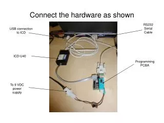
  1. RS232 Serial Cable USB connection to ICD ICD-U40 Programming PCBA Connect the hardware as shown To 9 VDC power supply

  2. PIN 1 of PIC to be programmed Programming PCBA Jumper setting for Program down loading Jumper Setting to connect to ICD

  3. Run down load program ‘cssload’ from the desk top

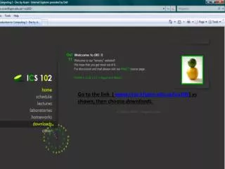
  4. 1) Click Browse to load hex program ’12F675 auto clk tune.hex’ 2) Click Write to Chip to down load the program Note: 9VDC power must be turned on Step 1 Step 2 A message “Programming completed. No Error” will be displayed”

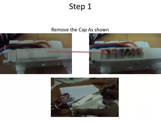
  5. 3) Turn off the power supply to the programming PCBA 4) Remove the 3 jumpers

  6. 5) Insert 2 jumpers to connect to the RS232 TX and RX

  7. Run HyperTerminal from the desk top

  8. 1) Click Cancel for new connection

  9. 1) File open and select ‘RS232’

  10. Check configuration

  11. Setting should be (9600, 8, None, 1, None)

  12. Power PIC programming PCBA and display will show ‘Input cmd:’

  13. Type ‘t’ to display calibration value and ‘w’ to write to EEPROM of PIC

More Related