Download
1 / 80
980 likes | 1.43k Vues
Marc T. Thompson, Ph.D. Thompson Consulting, Inc. 9 Jacob Gates Road Harvard, MA 01451 Phone: (978) 456-7722 Email: marctt@thompsonrd.com Website: http://www.thompsonrd.com. Jeff W. Roblee, Ph.D. VP of Engineering Precitech, Inc. Keene, NH www.ametek.com.

E N D
Marc T. Thompson, Ph.D. Thompson Consulting, Inc. 9 Jacob Gates Road Harvard, MA 01451 Phone: (978) 456-7722 Email: marctt@thompsonrd.com Website: http://www.thompsonrd.com Jeff W. Roblee, Ph.D. VP of Engineering Precitech, Inc. Keene, NH www.ametek.com Power Electronics Notes 29Thermal Circuit Modeling and Introduction to Thermal System Design
Summary • Basics of heat flow, as applied to device sizing and heat sinking • Use of thermal circuit analogies • Thermal resistance • Thermal capacitance • Examples • Picture window examples • Magnetic brake • Plastic tube in sunlight
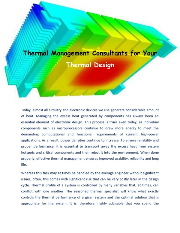
Capacitors • Electrolyte evaporation rate increases significantly with temperature increases and thus shortens lifetime Magnetic Components • Losses (at constant power input) increase above 100 °C • Winding insulation (lacquer or varnish) degrades above 100 °C Semiconductors • Unequal power sharing in parallel or series devices • Reduction in breakdown voltage in some devices • Increase in leakage currents • Increase in switching times Need for Component Temperature Control • All components (capacitors, inductors and transformers, semiconductor devices) have maximum operating temperatures specified by manufacturer • High operating temperatures have undesirable effects on components: 3
Temperature Control Methods •Control voltages across and current through components via good design practices • Snubbers may be required for semiconductor devices. • Free-wheeling diodes may be needed with magnetic components • Maximize heat transfer via convection and radiation from component to ambient • Short heat flow paths from interior to component surface and large component surface area. • Component user has responsibility to properly mount temperature-critical components on heat sinks. • Apply recommended torque on mounting bolts and nuts and use thermal grease between component and heat sink. • Properly design system layout and enclosure for adequate air flow 4
Heat Transfer • Heat transfer (or heat exchange) is the flow of thermal energy due to a temperature difference between two bodies • Heat transfers from a hot body to a cold one, a result of the second law of thermodynamics • Heat transfer is slowed when the difference in temperature between the two bodies reduces 5
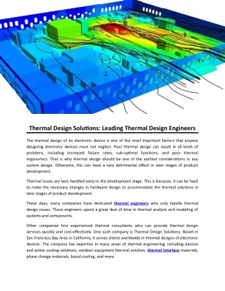
Intuitive Thinking about Thermal Modeling • Heat (Watts) flows from an area of higher temperature to an area of lower temperature • Heat flow is by 3 mechanisms • Conduction - transferring heat through a solid body • Convection - heat is carried away by a moving fluid • Free convection • Forced convection - uses fan or pump • Radiation • Power is radiated away by electromagnetic radiation • You can think of high- thermal conductivity material such as copper and aluminum as an easy conduit for conductive power flow…. i.e. the power easily flows thru the material
Thermal Circuit Analogy • Use Ohm’s law analogy to model thermal circuits • Thermal resistance • k = thermal conductivity (W/(mK)) • Thermal capacitance: analogy isn’t as straightforward • cp = heat capacity of material (Joules/(kg-K))
Thermal Circuit Analogy • Heat transfer can be modeled by thermal circuits • Using Ohm’s law analogy: Reference: M. T. Thompson, Intuitive Analog Circuit Design, Newnes, 2006. 8
Thermal Circuit Analogy • Elementary thermal network Reference: M. T. Thompson, Intuitive Analog Circuit Design, Newnes, 2006. 9
Thermal Resistance • Thermal resistance quantifies the rate of heat transfer for a given temperature difference • k = thermal coefficient (W/(mK)) • A = cross section (m2) • l = length (m) 10
Thermal Capacitance • Thermal capacitance is an indication of how well a material stores thermal energy • It is used when transient phenomena are considered • Analogy isn’t as straightforward • M = mass (kg) • cp = heat capacity of material (Joules/(kg-K)) 11
Heat Flow Mechanisms • Heat flows by 3 mechanisms; the driving force for heat transfer is the difference in temperature • Conduction • Convection • Free convection • Forced convection • 3. Radiation Reference: R. E. Sonntag and C. Borgnakke, Introduction to Engineering Thermodinamics, John Wiley, 2007 12
Conduction • Heat is transferred through a solid from an area of higher temperature to lower temperature • To have good heat conduction, you need large area, short length and high thermal conductivity • Example: aluminum plate, l = 10 cm, A=1 cm2, T2 = 25C (298K), T1= 75C (348K), k = 230 W/(m-K)
Thermal Conductivity of Selected Materials References: 1. B. V. Karlekar and R. M. Desmond, Engineering Heat Transfer, pp. 8, West Publishing, 1977 2. Burr Brown, Inc., “Thermal and Electrical Properties of Selected Packaging Materials”
Chip T j R R R q cs q sa q jc T T T T j c s a Case T c Heat sink T s Ambient Temperature T a Thermal Equivalent Circuits • Thermal equivalent circuit simplifies calculation of temperatures in various parts of structure. • Heat flow through a structure composed of layers of different materials Case Junction Sink Ambient + + + + P - - - - Isolation pad • Ti = Pd (Rjc+ Rcs + Rsa) + Ta • If there parallel heat flow paths, then thermal resistances combine as do electrical resistors in parallel. 15
Thermal Conductivity of Selected Materials Reference: International Rectifier, Application note N-1057, “Heatsink Characteristics”
Heat Capacity of Selected Materials • Heat capacity is an indication of how well a material stores thermal energy Reference: B. V. Karlekar and R. M. Desmond, Engineering Heat Transfer, West Publishing, 1977
Heat Capacity of Alloys Reference: http://www.engineeringtoolbox.com/specific-heat-metal-alloys-d_153.html
Convection • Convection can be free (without a fan) or forced (with a fan) Reference: International Rectifier, Application note N-1057, “Heatsink Characteristics”
Free Convection Reference: http://www.freestudy.co.uk/heat%20transfer/convrad.pdf 20
Heat Transfer Coefficient for Convection • Heat is transferred via a moving fluid • Convection can be described by a heat transfer coefficient h and Newton’s Law of Cooling: • Heat transfer coefficient depends on properties of the fluid, flow rate of the fluid, and the shape and size of the surfaces involved, and is nonlinear • Equivalent thermal resistance: Reference: B. V. Karlekar and R. M. Desmond, Engineering Heat Transfer, pp. 14, West Publishing, 1977
Free Convection • Heat is drawn away from a surface by a free gas or fluid • Buoyancy of fluid creates movement • For vertical fin: • A in m2, dvert in m • Example: square aluminum plate, A=1 cm2, Ta = 25C (298K), Ts = 75C (348K)
Free Convection Heat Transfer Coefficient (h) • For vertical fin: • Area A in m2, fin vertical height dvert in m
Forced Convection • With a fan Reference: International Rectifier, Application note N-1057, “Heatsink Characteristics”
Forced Convection • In many cases, heat sinks can not dissipate sufficient power by natural convection and radiation • In forced convection, heat is carried away by a forced fluid (moving air from a fan, or pumped water, etc.) • Forced air cooling can provide typically 3-5 increase in heat transfer and 3-5 reduction in heat sink volume • In extreme cases you can do 10x better by using big fans, convoluted heat sink fin patterns, etc.
Thermal Performance Graphs for Heat Sinks • Curve #1: natural convection (P vs. Tsa) • Curve #2: forced convection curve (Rsa vs. airflow) 1 2 Reference: http://electronics-cooling.com/articles/1995/jun/jun95_01.php 26
Radiation • Energy is transferred through electromagnetic radiation Reference: International Rectifier, Application note N-1057, “Heatsink Characteristics”
Radiation • Energy is lost to the universe through electromagnetic radiation • = emissivity (0 for ideal reflector, 1 for ideal radiator “blackbody”); = Stefan-Boltzmann constant • = 5.6810-8 W/(m2K4) • Example: anodized aluminum plate, = 0.8, A=1 cm2, Ta = 25C (298K), Ts = 75C (348K)
Radiation • Incident, reflected and emitted radiation; e.g. body in sunlight Reference: http://www.energyideas.org/documents/factsheets/PTR/HeatTransfer.pdf 29
Emissivity Reference: International Rectifier, Application note N-1057, “Heatsink Characteristics”
Emissivity Reference: International Rectifier, Application note N-1057, “Heatsink Characteristics”
Comments on Radiation • In multiple-fin heat sinks with modest temperature rise, radiation usually isn’t an important effect • Ignoring radiation results in a more conservative design • Effective heat transfer coefficient due to radiation for ideal blackbody ( = 1) at with surface temperature 350K radiating to ambient at 300K is hrad = 6.1 W/(m2K), which is comparable to free convection heat transfer coefficient • However, radiation between heat sink fins is usually negligible (generally they are very close in temperature)
IC Mounted to Heat Sink • Interfaces • Heat sink-ambient: convection (free or forced) • Heat sink-case of IC: conduction • Case – junction: conduction
Multiple Fin Heat Sink Reference: http://www.oldcrows.net/~patchell/AudioDIY/AudioDIY.html 34
IC Mounted to Heat Sink Reference: International Rectifier, Application Note AN-997
IC Mounted to Heat Sink --- Close-up • Thermal compound is often used to fill in the airgap voids Reference: International Rectifier, Application Note AN-997
IC Mounted to Heat Sink --- Contact Resistance vs. Torque (TO-247) Reference: International Rectifier, Application Note AN-997
IC Mounted to Heat Sink --- Contact Resistance vs. Interface Material (TO-247) Reference: International Rectifier, Application Note AN-997
IC Mounted to Heat Sink --- Contact Resistance vs. Interface Material (TO-247) • Dry vs. thermal compound vs. electrically-insulating pad Reference: International Rectifier, Application Note AN-997
T (t) j R q C s T a Transient Thermal Impedance •Heat capacity per unit volume Cv = dQ/dT [Joules /oC] prevents short duration high power dissipation surges from raising component temperature beyond operating limits. •Transient thermal equivalent circuit. Cs = CvV where V is the volume of the component. P(t) •Transient thermal impedance Z(t) = [Tj(t) - Ta]/P(t) •= π R Cs /4= thermal time constant • Tj(t = ) = 0.833 Po R 42
Use of Transient Thermal Impedance •Response for a rectangular power dissipation pulse P(t) = Po {u(t) - u(t - t1)}. • Tj(t) = Po { Z(t) - Z(t - t1) } •Symbolic solution for half sine power dissipation pulse. •P(t) = Po {u(t - T/8) - u(t - 3T/8)} ; area under two curves identical. •Tj(t) = Po { Z(t - T/8) - Z (t - 3T/8) } 43
Multilayer Structures •Multilayer geometry •Transient thermalequivalent circuit •Transient thermal impedance (asymptotic) of multilayer structure assuming widely separated thermal time constants. 44
Heat Sinks •Aluminum heat sinks of various shapes and sizes widely available for cooling components. • Often anodized with black oxide coating to reduce thermal resistance by up to 25%. • Sinks cooled by natural convection have thermal time constants of 4 - 15 minutes. • Forced-air cooled sinks have substantially smaller thermal time constants, typically less than one minute. •Choice of heat sink depends on required thermal resistance, Rsa, which is determined by several factors. • Maximum power, Pdiss, dissipated in the component mounted on the heat sink. • Component's maximum internal temperature, Tj,max •Component's junction-to-case thermal resistance, Rjc. •Maximum ambient temperature, Ta,max. • Rsa = {Tj,max - Ta,max}Pdiss - Rjc • Pdissand Ta,max determined by particular application. • Tj,max and Rjcset by component manufacturer. 45
Heat Conduction Thermal Resistance •Generic geometry of heat flow via conduction • Heat flow Pcond [W/m2] =kA (T2 - T1) / d = (T2 - T1) / R cond • Thermal resistance R cond = d / [k A] • Cross-sectional area A = hb • k = Thermal conductivity has units of W-m-1-oC-1 (kAl = 220 W-m-1-oC-1 ). • Units of thermal resistance are oC/W 46
Radiative Thermal Resistance •Stefan-Boltzmann law describes radiative heat transfer. •Prad = 5.7x10⁻⁸ EA [( Ts)4 -( Ta)4 ] ; [Prad] = [Watts] •E = emissivity; black anodized aluminum E = 0.9 ; polished aluminum E = 0.05 •A = surface area [m2] through which heat radiation emerges. •Ts = surface temperature [K] of component. Ta = ambient temperature [K]. • (Ts - Ta )/Prad = R,rad = [Ts - Ta][5.7x10⁻⁸EA {( Ts/100)4 -( Ta/100)4 }]-1 •Example - black anodized cube of aluminum 10 cm on a side. Ts = 120C and Ta =20C •R,rad = [393 - 293][(5.7) (0.9)(6x10⁻²){(393/100)4 - (293/100)4 }]-1 • R,rad = 2.2C/W 47
Convective Thermal Resistance •Pconv = convective heat loss to surrounding air from a vertical surface at sea level having height dvert [in meters] less than one meter. • Pconv = 1.34 A [Ts - Ta]1.25 dvert-0.25 • A = total surface area in [m2] •Ts = surface temperature [K] of component. Ta = ambient temperature [K]. •[Ts - Ta ]/Pconv = R,conv = [Ts - Ta ] [dvert]0.25[1.34 A (Ts - Ta )1.25]-1 •R,conv = [dvert]0.25 {1.34 A [Ts - Ta]0.25}-1 •Example - black anodized cube of aluminum 10 cm on a side. Ts = 120C and Ta = 20C. •R,conv = [10-1]0.25([1.34] [6x10⁻²] [120 - 20]0.25)-1 •R,conv = 2.2 C/W 48
Combined Effects of Convection and Radiation •Heat loss via convection and radiation occur in parallel. •Steady-state thermal equivalent circuit • R,sink = R,rad R,conv / [R,rad + R,conv] • Example - black anodized aluminum cube 10 cm per side • R,rad = 2.2 C/W and R,conv = 2.2C/W • R,sink = (2.2) (2.2) /(2.2 + 2.2) = 1.1C/W 49
Cost for Various Heat Sink Systems • Note: heat pipe and liquid systems require eventual heat sink Reference: http://www.electronics-cooling.com/Resources/EC_Articles/JUN95/jun95_01.htm