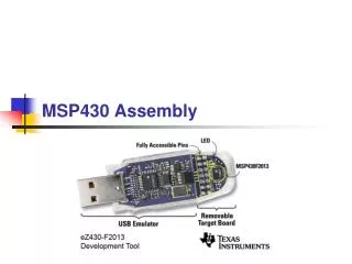
MSP430 Project
MSP430 Project. Group Members Rosie West Quest Tibbs John Trinos. Objectives. To solder components to the board and program the MSP430 microcontroller to display the message “Hello” on the LCD.


MSP430 Project
E N D
Presentation Transcript
MSP430 Project Group Members Rosie West Quest Tibbs John Trinos
Objectives • To solder components to the board and program the MSP430 microcontroller to display the message “Hello” on the LCD. • To create a sensor circuit and program the MSP430 to display the measurements taken by the sensor.
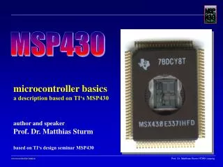
MSP430 Overview • Captures analog signals • Converts them to digital values • Processes this data and displays it on an LCD panel
MSP430 • Low Supply-Voltage Range, 1.8 V to 3.6 V • Ultralow-Power Consumption: Active Mode: 280 µA at 1 MHz, 2.2 V • Wake-Up From Standby Mode in less than 6 µs • 16-Bit RISC Architecture, 125-ns Instruction Cycle Time • 12-Bit A/D Converter With Internal Reference, Sample-and-Hold and Autoscan Feature • 16-Bit Timer_B With Seven Capture/Compare-With-Shadow Registers • 16-Bit Timer_A With Three Capture/Compare Registers • On-Chip Comparator • Serial Communication Interface (USART), Select Asynchronous UART or Synchronous SPI by Software: • Two USARTs (USART0, USART1) — MSP430x44x Devices • Brownout Detector • Supply Voltage Supervisor/Monitor With Programmable Level Detection • Serial Onboard Programming, No External Programming Voltage Needed Programmable Code Protection by Security Fuse • Integrated LCD Driver for Up to 160 Segments • 60KB+256B Flash Memory, 2KB RAM
AD590 Temperature Sensor • Linear current output: 1 µA/K • Wide temperature range: -55°C to +150°C • Probe compatible ceramic sensor package • 2-terminal device: voltage in/current out • Laser trimmed to ±0.5°C calibration accuracy (AD590M) • Excellent linearity: ±0.3°C over fullrange (AD590M) • Wide power supply range: 4 V to 30 V • Sensor isolation from case
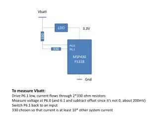
Sensor Circuit Approach • We decided to use both of the sample temperature sensors to decrease the amount of noise in the measurement. • We also used the suggestions Dr. Green gave us in class and used a turnpot resistor in series with a resistor to produce 1 mV/ºK going into a noninverting op amp with a gain of 5, which was achieved by using resistors so that V0=(1+Rfb/Rin)Vin .
Modifications to Sensor.c • The only needed adjustments to the code was to change the A/D converter value. • Our value was found to be .0605765 instead of .0613