Low Power Temperature Sensor Circuit with MSP430: Design, Testing, and Implementation
This project details the construction and testing of a low-power temperature sensor circuit using an MSP430 microcontroller. The goals include building a circuit board, programming the MSP430 to display a "Hello" message, and constructing an AD590-based sensor circuit for accurate temperature measurements in Celsius and Fahrenheit. The design emphasizes ultra-low power consumption, extending battery life, and includes features like LCD interface and PC connection. The project combines hands-on soldering and programming experience, focusing on practical engineering skills.


Low Power Temperature Sensor Circuit with MSP430: Design, Testing, and Implementation
E N D
Presentation Transcript
GROUP #2 Adam Fraprie Ed Shouse MSP430 Project John Glass Dr. Green
Objectives • Construct Circuit Board • MSP430 • Load and Test “Hello” Software • Demo.c • Construct Sensor Circuit • AD590 • Load and Test Sensor Software • Sensor.c • Accurately Measure Temperature in Celsius and Fahrenheit
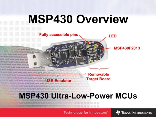
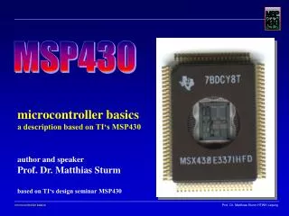
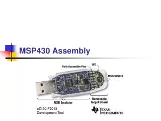
MSP430 • Ultra Low Power Architecture • Extends Battery Life • 0.1μA RAM Retention • 16-bit CPU • Low Cost
Completed Circuit Board • LCD • Power Supply • MSP430 • PC Connection • Reset • Input • Output • Capacitors
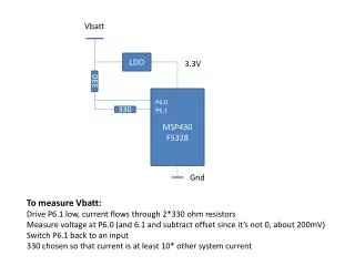
AD590 • Accuracy • +/- 0.5º C • +/- 0.9º F • Power Range • 4V – 30V • Temperature Range • -55º C -- 150º C • -67º F -- 302º F • 2 Terminal Device • Voltage in (+) • Current out (-) • 1μA/K
Software Filter // Filter the signal with a 4th order moving average SIGK = (XIN + XIN1 + XIN2 + XIN3 + XIN4 + XIN5 + XIN6 + XIN7)*.125; XIN7 = XIN6; XIN6 = XIN5; XIN5 = XIN4; XIN4 = XIN3; XIN3 = XIN2; XIN2 = XIN1; XIN1 = XIN; CDEG = (SIGK - 273.2); FDEG = 1.8*CDEG + 32.0; // converting from deg C to deg F
New Experiences • Soldering • Construction of Practical Circuit • Programming Flash Memory • Calibration Using Potentiometer • Engineering Team Building • FUN!!!!
Questions ??? ? ? ? ? ? ? ? ? ? ? ?