Switching and Forwarding
This text explores the concepts of switching and forwarding in network architectures, focusing on multi-access and point-to-point links. It discusses how multi-access links, such as Ethernet and wireless connections, allow multiple nodes to share a single physical link, along with their limitations. It contrasts this with point-to-point links that connect only two nodes. Key topics include the role of switches, star topology networks, circuit switching, and packet switching, emphasizing their advantages, disadvantages, and operational characteristics in network communication.

Switching and Forwarding
E N D
Presentation Transcript
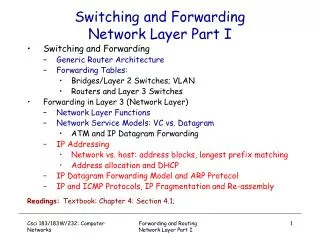
Switching and Forwarding Sections 3.1
Connecting More Than Two Hosts • Multi-access link: Ethernet, wireless • Single physical link, shared by multiple nodes • Limitations on distance and number of nodes • Point-to-point links: fiber-optic cable • Only two nodes (separate link per pair of nodes) • Limitations on the number of adapters per node point-to-point links multi-access link
Beyond Directly-Connected Networks • Switched network • End hosts at the edge • Network nodes switch traffic • Links between the nodes • Multiplexing • Many end hosts communicate over the network • Traffic shares access to the same links
What is a Switch • A mechanism to interconnect links to form a larger network • Multi-input, multi-output • Transfers packets from an input to one or more outputs • Adds star topology network to • point-to-point • bus (Ethernet) • ring (802.5 and FDDI) • ad hoc
Properties of Star Topology • Large geographic scope networks can be built by interconnecting a number of switches • connect switches to each other and to hosts using point-to-point links • A new host connected to a switched network does not necessarily degrade performance of already connected hosts • Every host has its own link to the switch • Hosts can transmit at full link bandwidth • Switch can be designed to handle aggregate bandwidth • In contrast, all hosts on an Ethernet cannot transmit continuously at 10Mbps (share medium)
Circuit Switching (e.g., Phone Network) • Source establishes connection to destination • Nodes along the path store connection info • Nodes may reserve resources for the connection • Source sends data over the connection • No destination address, since nodes know path • Source tears down connection when done
Time-division Each circuit allocated certain time slots (in the figure 6 circuits) Frequency-division Each circuit allocated certain frequencies Circuit Switching: Multiplexing a Link frequency time time
Virtual Circuit Switching • Explicit connection setup (and tear-down) phase • Subsequence packets follow same circuit • Sometimes called connection-oriented model • Each switch maintains a VC table • Analogy: phone call
Connection Setup Phase Establish “connection state” in each of the switches between the source and destination hosts • an entry in a “VC table” in each switch through which the connection passes. Fields of each entry are: • a virtual circuit identifier (VCI) that uniquely identifies the connection at this switch and that will be carried inside the header of incoming packets that belong to this connection • incoming interface on which packets for this VC arrive • outgoing interface in which packets for this VC leave • VCI that will be used for outgoing packets (a potentially different from incoming VCI)
Virtual Circuit Table (switch 1, port 2) 0 0 0 1 3 11 3 1 3 1 2 Switch 1 Switch 2 2 2 2 5 0 7 Switch 3 3 1 Host B Host A 4 Example Table
Virtual Circuit Model • Typically wait full RTT for connection setup before sending first data packet. • While the connection request contains the full address for destination, each data packet contains only a small identifier, making the per-packet header overhead small. • If a switch or a link in a connection fails, the connection is broken and a new one needs to be established. • Connection setup provides an opportunity to reserve resources.
Advantages of Circuit Switching • Guaranteed bandwidth • Predictable communication performance • Not “best-effort” delivery with no real guarantees • Simple abstraction • Reliable communication channel between hosts • No worries about lost or out-of-order packets • Simple forwarding • Forwarding based on time slot or frequency • No need to inspect a packet header • Low per-packet overhead • Forwarding based on time slot or frequency • No IP (and TCP/UDP) header on each packet
Disadvantages of Circuit Switching • Wasted bandwidth • Bursty traffic leads to idle connection during silent period • Unable to achieve gains from statistical multiplexing • Blocked connections • Connection refused when resources are not sufficient • Unable to offer “okay” service to everybody • Connection set-up delay • No communication until the connection is set up • Unable to avoid extra latency for small data transfers • Network state • Network nodes must store per-connection information • Unable to avoid per-connection storage and state
Packet Switching (e.g., Internet) • Packet Switching: statistical multiplexing of links • Data traffic divided into packets • Each packet contains a header (with address) • Packets travel separately through network • Packet forwarding based on the header • Network nodes may store packets temporarily • Destination reconstructs the message
Packet Switching (cont. I) • No connection setup phase • Each packet forwarded independently • Sometimes called connectionless model • Analogy: postal system • Each switch maintains a forwarding (routing) table
Datagram Switching (cont. II) • Forwarding Table (switch 1)
Datagram Model vs. Virtual Circuit Model • There is no round trip delay waiting for connection setup; a host can send data as soon as it is ready. • Source host has no way of knowing if the network is capable of delivering a packet or if the destination host is even up. • Since packets are treated independently, it is possible to route around link and node failures. • Since every packet must carry the full address of the destination, the overhead per packet is higher than for the connection-oriented model.
Routing Alternative: Source Routing • All information required to switch a packet across the network is provided by the source host • an ordered list of switch ports in header • in every switch on the route, rotate the list so that next switch output port is always at the front of the list