Switching and Forwarding
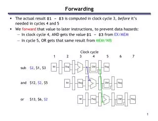
Switching and Forwarding. Problems. 1500m limit on length of network Contention, collisions Limited number of hosts Communicate between hosts that do not have a direct connection. Scalable Networks. Switch: Forwards packets from input port to output port;


Switching and Forwarding
E N D
Presentation Transcript
Problems • 1500m limit on length of network • Contention, collisions • Limited number of hosts • Communicate between hosts that do not have a direct connection
Scalable Networks • Switch: Forwards packets from input port to output port; • port selected based on destination address in packet header.
Advantages • Can build networks that cover large geographic area • Can build networks that support large numbers of hosts • Can add new hosts without affecting performance of existing hosts
Source Routing • Address contains sequence of ports on path from source to destination. 2 1 1 Where does it go?
Source Routing • Source host must know entire topology • Variable size header causes switches to be slow • Approaches include rotation, stripping, pointers • Impractical for large networks
Header entering D C B A D C B A Ptr D C B A switch Header leaving A D C B D C B Ptr D C B A switch (a) (b) (c) Rotation, stripping and pointer
Virtual Circuit Switching • Explicit connection setup (and tear-down) phase • Subsequent packets follow same circuit • Analogy: phone call • Sometimes called connection-oriented model • Each switch maintains a VC table. • Each circuit can be identified and handled differently (buffers, QoS)
8 16 8 Variable 16 8 Flag Frame Flag Address Control Data (0x7E) checksum (0x7E) Virtual Circuits • ATM • X.25 • Allocates buffers before connecting • Frame Relay
Datagrams • No connection setup phase • Each packet forwarded independently • Analogy: postal system • Sometimes called connectionless model • Each switch maintains a forwarding (routing) table
Virtual Circuit versus Datagram Virtual Circuit Model: • Typically wait full RTT for connection setup before sending first data packet. • While the connection request contains the full address for destination, each data packet contains only a small identifier, making the per-packet header overhead small. • If a switch or a link in a connection fails, the connection is broken and a new one needs to be established. • Connection setup provides an opportunity to reserve resources.
Datagram Model: • There is no round trip time delay waiting for connection setup; a host can send data as soon as it is ready. • Source host has no way of knowing if the network is capable of delivering a packet or if the destination host is even up. • Since packets are treated independently, it is possible to route around link and node failures. • Since every packet must carry the full address of the destination, the overhead per packet is higher than for the connection-oriented model.
Congestion vs Contention • Contention occurs when multiple packets are queued on same output port • Congestion when switch runs out of buffers and must drop a packet • Virtual Circuits avoid congestion by negotiating on setup • Datagrams use buffers more efficiently
Performance • Switches can be built from a general-purpose workstations; will consider special-purpose hardware later.
Performance • Aggregate bandwidth • 1/2 of the I/O bus bandwidth • capacity is shared among all hosts connected to switch • example: 800Mbps bus can support 8 T3 ports • Packets-per-second • must be able to switch small packets • 15,000 packets-per-second is an achievable number • 66μsec/packet • 50ns memory = 128 memory accesses • example: 64-byte packets implies 7.69Mbps