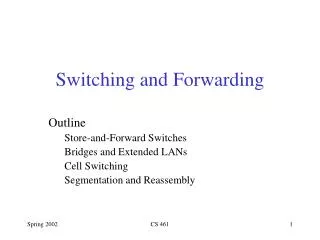
EE 122: Switching and Forwarding
250 likes | 394 Vues
This document provides a comprehensive overview of Direct Link Networks and switching principles in data communication. It discusses the functionality of the data link layer, framing techniques, error detection methods, and concepts like packet switching and forwarding. Additionally, it covers the limitations of direct link networks related to distance, host numbers, and bandwidth sharing among nodes. The text also contrasts bridge and router functionalities, mentioning various forwarding and switching techniques while emphasizing reliability and performance challenges in network communication.

EE 122: Switching and Forwarding
E N D
Presentation Transcript
EE 122: Switching and Forwarding Kevin Lai September 23, 2002
Direct Link Network Review • Data link layer presents a single media (e.g., single wire) network model • Problem and solutions • Framing • character stuffing, byte counting, bit stuffing, clocked framing • Error detection • parity, checksum, CRC • Reliability • stop and go, sliding window • solutions also apply to similar problems in higher layers • problems can not be completely solved at data link layer • only implemented in data link layer as optimization laik@cs.berkeley.edu
Limitations of Direct Link Networks • distance • distance increases propagation delay • large propagation delay causes large coordination delay • e.g., Ethernet collision detection requires 2*prop_delay • number of hosts • More hosts increases the probability of collisions • collisions decrease efficiency of link • bandwidth • bandwidth of link is shared among all connected nodes • single media type • different media (e.g., fiber, Ethernet, wireless) have different tradeoffs for performance, cost, etc. laik@cs.berkeley.edu
Direct Link Networks v.s. Switching n links Single link Switch Emulatesclique Direct Link Network Switched Network laik@cs.berkeley.edu
Definitions • switch (aka bridge) • does switching • operates at data link layer • router also does switching, but at network layer • switching consists of • forwarding • read data from input links, • decide which output link to forward on, and • examine packet header or incoming circuit, and • look up in forwarding table • transmit it on one of the output links (unicast) • routing • how the switch/router builds up its forwarding table laik@cs.berkeley.edu
Properties • spans larger physical area than direct link network (DLN) • can connect multiple switches together • supports more hosts than DLN • hosts on separate links can transmit at same time • higher aggregate bandwidth than DLN • approaches (n/2)*b instead of b, n = number of switched links, b = bandwidth of one link • supports more than one media type • more expensive for bridge than router laik@cs.berkeley.edu
Bridge/Router Comparison • Router interconnects different link layer protocols more easily Router Switch Ethernet E-to-E Ethernet Ethernet E-to-IP IP-to-E Ethernet E-to-8 802.11b 802.11b 802.11b 8-to-IP IP-to-8 802.11b E-to-A ATM ATM ATM A-to-IP IP-to-A ATM E-to-S SONET SONET SONET S-to-IP IP-to-S SONET O(n2) convertersn = different link types O(n) converters laik@cs.berkeley.edu
Forwarding Techniques • packet switching • aka [packet|datagram|connectionless] [switching|forwarding] • source routing • virtual circuit switching • aka virtual circuit forwarding • circuit switching • despite names, all ways for switch to decide which output port to forward data laik@cs.berkeley.edu
Packet Switching • Data is separated into packets • Each packet is forwarded independently of previous packets • packets between two hosts can follow different paths • On link failure, adjoining switches select new route and continue forwarding packets • Statistical multiplexing • any one host may use 100% of a link’s bandwidth laik@cs.berkeley.edu
Statistical Multiplexing v.s. Resource Reservations Advantage Problem • Reserve explicit amount of resources (e.g., bandwidth) • get exactly that amount • Statistical multiplexing: get whatever is available 10Mb/s 10Mb/s 10Mb/s 10Mb/s ... ... H0 H0 ... StatisticalMultiplexing ... 10Mb/s / 10Mb/s 10Mb/s / 10Mb/s S S 10Mb/s 10Mb/s ... congestion,packet loss H9 ... H9 10Mb/s 10Mb/s low utilization 1Mb/s 1Mb/s ... ... H0 H0 ResourceReservations ... ... 10Mb/s / 10Mb/s 1Mb/s / 10Mb/s S S 1Mb/s 0Mb/s 1Mb/s 1Mb/s ... ... H9 H9 laik@cs.berkeley.edu
Packet Switching Operation • Each switch maintains a forwarding table • forwarding entry: (address, output port) • Upon packet arrival • input port forwards the packet to the output port whose address matches packet’s destination address • exact match • longest prefix match • forwarding entry: (address prefix, output port) • forward packet to the output port whose address matches packet’s destination address in the longest number of bits 128.16.120.111 1 12.xxx.xxx.xxx 1 12.82.xxx.xxx 2 12.82.100.101 1 128.16.120.111 2 laik@cs.berkeley.edu
Packet Switching Properties • Expensive forwarding • forwarding table size depends on number of different destinations • must lookup in forwarding table for every packet • Robust • link and router failure may be transparent for end-hosts • High bandwidth utilization • statistical multiplexing • No service guarantees • Network allows hosts to send more packets than available bandwidth congestion dropped packets laik@cs.berkeley.edu
Source Routing • Each packet specifies the sequence of routers, or alternatively the sequence of output ports, from source to destination source 1 1 2 2 1 1 3 3 2 2 4 4 3 3 4 4 4 3 4 1 1 2 2 4 3 4 3 3 4 3 4 4 4 laik@cs.berkeley.edu
Source Routing (cont’d) • Gives the source control of the path • Not scalable • Packet overhead proportional to the number of routers • Typically, require variable header length which is harder to implement • Hard for source to have complete information • Loose source routing sender specifies only a subset of routers along the path laik@cs.berkeley.edu
Virtual Circuit (VC) Switching • Packets not switched independently • establish virtual circuit before sending data • Forwarding table entry • (input port, input VCI, output port, output VCI) • VCI – Virtual Circuit Identifier • Each packet carries a VCI in its header • Upon a packet arrival at interface i • Input port uses i and the packet’s VCI v to find the routing entry (i, v, i’, v’) • Replaces v with v’ in the packet header • Forwards packet to output port i’ laik@cs.berkeley.edu
1 11 5 7 VC Forwarding: Example in-VCI out-VCI out in … … … … in-VCI out-VCI out in 1 7 4 1 … … … … … … … … destination source 3 5 4 11 … … … … 1 1 2 2 1 1 3 3 2 2 4 4 3 3 4 4 1 1 2 2 3 3 4 4 in-VCI out-VCI out in … … … … 2 11 3 7 … … … … laik@cs.berkeley.edu
VC Forwarding (cont’d) • A signaling protocol is required to set up the state for each VC in the routing table • A source needs to wait for one RTT (round trip time) before sending the first data packet • Can provide per-VC QoS • When we set the VC, we can also reserve bandwidth and buffer resources along the path laik@cs.berkeley.edu
Virtual Circuit Switching Properties • Less expensive forwarding • forwarding table size depends on number of different circuits • must lookup in forwarding table for every packet • Much higher delay for short flows • 1 RTT delay for connection setup • Less Robust • end host must spend 1 RTT to establish new connection after link and router failure • Flexible service guarantees • either statistical multiplexing or resource reservations laik@cs.berkeley.edu
Circuit Switching • Packets not switched independently • establish circuit before sending data • Circuit is a dedicated path from source to destination • e.g., old style telephone switchboard, where establishing circuit means connecting wires in all the switches along path • e.g., modern dense wave division multiplexing (DWDM) form of optical networking, where establishing circuit means reserving an optical wavelength in all switches along path • No forwarding table laik@cs.berkeley.edu
Circuit Switching Properties • Cheap forwarding • no table lookup • Much higher delay for short flows • 1 RTT delay for connection setup • Less robust • end host must spend 1 RTT to establish new connection after link and router failure • Must use resource reservations laik@cs.berkeley.edu
Forwarding Comparison laik@cs.berkeley.edu
Routing • Update forwarding/routing tables • Manual configuration • simple, error prone, work for administrator • Learning bridges • all that is needed for single bridge • Spanning Tree • necessary for multiple bridges • Described in internetworking section • Distance Vector • Link State laik@cs.berkeley.edu
Learning Bridges 1 1 2 2 3 3 laik@cs.berkeley.edu
Learning Bridge Problem H1 0 1 H0 B0 2 1 B1 2 0 1 0 B2 0 1 B3 laik@cs.berkeley.edu
Summary • Switching • overcome limitations of direct link networks • Forwarding techniques • packet switching • source routing • virtual circuit switching • circuit switching • Routing techniques laik@cs.berkeley.edu