Download
1 / 14

E N D
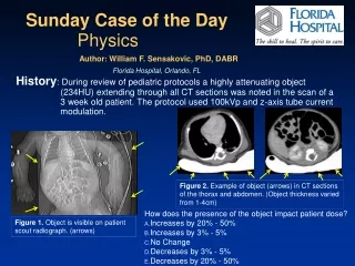
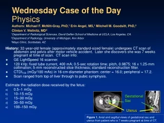
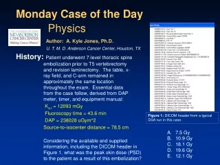
History: Patient underwent 7-level thoracic spine embolization prior to T5 vertebrectomy and revision laminectomy. The table, x-ray field, and C-arm remained in approximately the same location throughout the exam. Essential data from the case follow, derived from DAP meter, timer, and equipment manual: Ka,r= 12093 mGy Fluoroscopy time = 43.6 min DAP = 238028 uGym^2 Source-to-isocenter distance = 78.5 cm Monday Case of the Day Physics Author: A. Kyle Jones, Ph.D. U. T. M. D. Anderson Cancer Center, Houston, TX Figure 1: DICOM header from a typical DSA run in this case. • 7.5 Gy • 10.9 Gy • 18.1 Gy • 19.6 Gy • 12.1 Gy Considering the available and supplied information, including the DICOM header in Figure 1, what was the peak skin dose (PSD) to the patient as a result of this embolization?
Discussion:Calculating the Peak Skin Dose (PSD) from Ka,r involves several intermediate steps: 1. Inverse-square correction for location of patient compared to the Interventional Reference Point (IRP) 2. Conversion from Ka,skin (peak skin air kerma) to Dskin by (a) converting from Ka to skin dose and (b) application of the backscatter factor (BSF)
1.Inverse-square correction from IRP to patient’s skin surface The “Distance Source to Patient” in the DICOM header (Fig. 2, Tag 0x00181111) is derived from the table position at the time of image acquisition/creation, and is given in units of mm. For cases in which the C-arm angle is not varied, this distance remains fairly constant throughout the study. For this case, the distance is 809.0 mm, or 80.9 cm. Some DICOM tags may be unclear in their meaning, or valuable information may be stored in private tags accessible through external software (e.g. ImageJ1). Most, if not all, manufacturers’ DICOM Conformance Statements can be found on their respective websites. Figure 2: DICOM header from a typical DSA run in this case.
1.Inverse-square correction from IRP to patient’s skin surface The IRP is defined by the IEC2 as a point 15 cm on the source side of isocenter. Equipment manuals specify the source-to-isocenter distance, the location of the IRP, or both. For this equipment, the source-to-isocenter distance is 78.5 cm, thus the IRP is located 78.5 cm – 15 cm = 63.5 cm from the x-ray source. Therefore, the inverse-square correction can be calculated as: Figure 3: Specification of source-to-isocenter distance/IRP. This information can be found in the technical specifications for your equipment, either as the source-to-isocenter distance or the IRP. This specific example is from the Siemens Axiom Artis owner’s manual.
2a.Conversion from Ka,skin to Dskin The f-factor (fmed) is used to convert from exposure (X) to Dtissue. In our case, Ka,r is in units of Gy, so we can either convert Ka,r to X or we can convert the f-factor into a Dtissue/Dair conversion factor as follows: Figure 5: Dmed/Dair in diagnostic radiology. Figure 4: F-factors (fmed) in diagnostic radiology. From Johns and Cunningham.3
2b.Application of the backscatter factor (BSF) Photons in the diagnostic energy range are frequently scattered backwards upon their first interaction in tissue, resulting in further deposition of dose in the skin. The BSF is a strong function of field size, beam quality, and attenuating material, and a weak function of SOD. In the diagnostic energy range (50-150 keV), the BSF ranges from 1.25 to 1.57 in soft tissue.4 Since the BSF depends strongly on beam quality and field size, we must determine these quantities. We can see from the DICOM header (Fig. 6, 0x00180060) that the kVp for this particular DSA series was 97, and review of the image data and Exam Protocol from this case demonstrates that the kVp remains within about a 10 kVp range throughout the study. Figure 6: DICOM header from a typical DSA run in this case.
2b.Application of the BSF We can calculate the x-ray field size in the detector plane from the listed collimator positions in the DICOM header (Fig. 1, 0x00181702, 0x00181704, 0x00181706, 0x00181708) and the pixel size in Tag 0x00181164. The collimator boundaries are: Left: 10 Right: 1430 Upper: 11 Lower: 1429 Pixel size: 0.154 mm (1430 – 10) x 0.154 = 218.7 mm (1429 – 11) x 0.154 = 218.4 mm Finally, we can determine the x-ray field size in the patient plane by correcting by the Estimated Radiographic Magnification Factor (SID/SOD) in 0x00181114, which is equal to 1.41: 218.7 mm / 1.41 = 15.5 cm 218.4 mm / 1.41 = 15.5 cm Figure 7: BSF in diagnostic radiology.4
2b.Application of the BSF Using our kVp of approximately 100 and our field size of approximately 15 cm x 15 cm, we can interpolate to find a value for the BSF in tissue of 1.41.4 Applying all of the corrections we can calculate the estimated PSD from this case:
Caveats:Several assumptions were made during the calculation, based on a review of the image data from the case: 1. X-ray field size remained relatively constant throughout the case. 2. C-arm angle remained relatively constant throughout the case. 3. Table position remained relatively constant throughout the case. It is possible (and necessary in the absence of cumulative Ka,r data) to calculate the contribution to skin dose from each acquisition run individually using the methods discussed in this case using DAP values reported in the DICOM header (0x0018115e). However, this approach is much more complex and more susceptible to calculation errors. Also, determining the contribution to PSD from fluoroscopy using this method would necessitate a dose report from the system or estimation by the physicist. Using the method outlined here, small variations in field size, kVp, and possibly table position throughout the exam may introduce a small amount of uncertainty into the final PSD estimate. However, there are other potentially large sources of uncertainty, such as the energy dependence and calibration of the DAP meter. It is also important to note that even moderate variations in C-arm angle will not greatly affect calculation of the PSD, as substantial x-ray field overlap will occur. Large CC or lateral angles may, however, increase PSD due to increased tissue penetration thickness, but this will be reflected in Ka,r
Caveats 2: Other sources of uncertainty in this case include the proximity of the skin to the thoracic vertebrae. This may result in a higher BSF than the estimate derived previously. There may also be a large difference in technique factors for fluoroscopic imaging compared to acquisition imaging. This may include lower kVp values and large amounts of Cu filtration in the x-ray beam. Thus, the BSF for fluoroscopic imaging may be different than for acquisition imaging. However, in this case acquisition imaging was the major contributor (> 80%) to PSD, as is true in many complex cases. Therefore, a single BSF was used to simplify the calculations for the purpose of the Case of the Day. In practice, separate BSF can be used for fluoroscopic and acquisition imaging, as well as individual acquisition runs. Finally, it is important that DAP meters be checked for accuracy and energy dependence during acceptance testing and checked for accuracy during annual quality control testing, and recalibrated or replaced if necessary.5-8 It is also vital to record available dose descriptors9 and cases with PSD exceeding certain limits should be flagged for follow-up9-10 (the Society of Interventional Radiology recommends the following thresholds10: PSD > 3 Gy, Ka,r > 5 Gy, KAP > 500 Gy-cm2). Exam protocols produced by some manufacturers (Fig. 8) may be of great help when conducting a peak skin dose reconstruction, and DICOM Structured Reporting for dose11 may soon be available.
Figure 8: Example of information available in Exam Protocol (page 2 of 2).
References/Bibliography: National Institutes of Health, http://rsbweb.nih.gov/ij/, Accessed 11/18/2009. International Electrotechnical Commission, IEC Standard 60601-2-43. Johns HE and Cunningham JR. The Physics of Radiology, 4th ed. Charles C. Thomas, Springfield, IL, 1983. Petoussi-Henzss N, et al. Calculation of backscatter factors for diagnostic radiology using Monte Carlo methods, Phys. Med. Biol. 43:2237–2250, 1998. Shrimpton PC, Wall BF, Jones DG, and Fisher ES. The measurement of energy imparted to patients during diagnostic X-ray examinations using the Diamentor exposure-area product meter, Phys Med Biol 29:1199-1208, 1984. Shrimpton PC and Wall BF. An evaluation of the Diamentor transmission ionisation chamber in indicating exposure-area product (Rcm2) during diagnostic radiological examinations, Phys Med Biol 27:871-78, 1982.
References/Bibliography: Larsson JP, Persliden J, Sandborg M, and AlmCarlsson G. Transmission ionization chambers for measurements of air collision kerma integrated over beam area. Factors limiting the accuracy of calibration, Phys Med Biol 41:2381-2398, 1996. GfirtnerH, Stieve F, and Wild J. A new Diamentor for measuring kerma-area product and air-kerma simultaneously, Med Phys 24(12):1954-59, 1997. Miller DL, et al. Quality improvement guidelines for recording patient radiation dose in the medical record, J VascIntervRadiol. 15:423–429, 2004. Stecker MS, et al. Guidelines for patient radiation dose management, J VascIntervRadiol. 20:S263–S273, 2009. Digital Imaging and Communications in Medicine (DICOM). Supplement 94 – Diagnostic X-Ray Radiation Dose Reporting (Dose SR), ftp://medical.nema.org/medical/dicom/final/sup94_ft.pdf, Accessed 11/19/2009. A. Kyle Jones would like to acknowledge the contribution of Phil Rauch, M.S. in reviewing this Case of the Day