Download
1 / 13
140 likes | 566 Vues
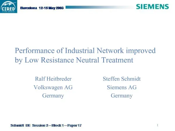
Performance of Industrial Network improved by Low Resistance Neutral Treatment. Ralf Heitbreder Volkswagen AG Germany. Steffen Schmidt Siemens AG Germany. Structure of 6 kV system. 110 kV. 6 kV switchgear (with circuit breakers). 0.4 kV busbar.

E N D
Performance of Industrial Network improved by Low Resistance Neutral Treatment Ralf Heitbreder Volkswagen AG Germany Steffen Schmidt Siemens AG Germany
Structure of 6 kV system 110 kV 6 kV switchgear(with circuit breakers) 0.4 kV busbar 6 kV unit substation (with load interrupter switches and HV fuses)
Initial state (isolated neutral) • unreliable operation of transient earth fault relays • high overvoltages (transient and power frequent) • high fault current over a long time virtually every earth fault results in multi-pole fault • high voltage dips in 0.4 kV system in case of multi-pole 6 kV fault • man power needed for fault location and switch off
Steps of Investigation • Measurements for data acquisition • Zero sequence impedance; Reduction factor of cable shield • Earthing and touch Voltages • Calculation of earth fault currents • Comparison of variants of neutral treatment • Effects on operation; Risk of fault propagation • Devices for fault detection and protection • Neutral devices • Compliance with touch voltage criteria • Installation of proposed variant of neutral treatment • Commissioning and earth fault test
Measurements for data acquisition I Current source test 6 kV cable NYFG(b)Y I U I A V A test sheath • Results: • Z0£ 1,5 W/km + j 1,5 W/km • rE = 0,60 ... 0,80 • UE£ 20 V/kA • UB£ 10 V/kA measurement of earthing measurement of earthing I and touch voltages and touch voltages A earth V V feeding station remote station
Improved operation with isolated neutral • no interruption of supply • no cost for neutral devices • high fault current over a long time risk of multi-pole fault • high overvoltages (transient and power frequent) risk of double fault • new capacitive directional earth fault relays necessary • man power needed for fault location and switch off
Operation with earth fault compensation • no interruption of supply • small earth fault current low risk of multi-pole fault • high overvoltages (transient and power frequent) risk of double fault • new wattmetric earth fault relays and window-type transformers necessary • high costs for neutral earthing transformer and arc suppression coil • man power needed for fault location and switch off
Low impedance earthing 2000 A • fast fault clearing low risk of multi-pole fault • no transient overvoltages low risk of double fault • existing overcurrent-time relays with phase fault detection can be used • setting of phase fault detection must changed to • smaller starting currents (to detect earth faults) and • higher delay times (to prevent tripping by inrush currents) • voltage dips of up to 10 % in 0.4 kV system in case of 6 kV earth faults • unselective or no tripping of HV fuses
Low impedance earthing 500 A • fast fault clearing and low fault current low risk of multi-pole fault • no transient overvoltages low risk of double fault • low voltage dips in 0.4 kV system in case of 6 kV earth faults • new overcurrent-time relays with earth fault detection necessary • unselective or no tripping of HV fuses
Comparison of Investment Costs Isolated neutral Earth fault compensation Low impedance earthingIk1 = 2000 A Low impedance earthingIk1 = 500 A
Equipment used for low impedance earthing Neutral earthing transformer Neutral resistor
Results of the short-circuit test voltages 6 kV system earth fault current voltages 400 V system 0,4 kV 6 kV
Operational experience • low impedance earthing (Ik1 = 500 A) is in operation for more than 2 years • 2 earth fault were selectively cleared by protection relays • no unselective tripping in response to earth fault starting • no sensible voltage dips in 0.4 kV system during 6 kV earth faults