Download
1 / 32
320 likes | 563 Vues
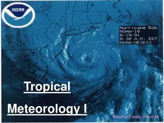
Radars and Meteorology Shri S.H. Damle Indian Institute of Tropical Meteorology Pune. Radar & Meteorology. Historical Back Ground Basic concept of Radar Nikola Tesla – 1900 Article in Century Magazine.

E N D
Radars and Meteorology Shri S.H. Damle Indian Institute of Tropical Meteorology Pune
Radar & Meteorology Historical Back Ground Basic concept of Radar Nikola Tesla – 1900 Article in Century Magazine
Some british & German Patents on Detection & Ranging of Remote metallic objects by Radio Waves – 1900-1906 • First practical Demonstration of Ranging using FM-CW transmitter. Dec 1924 Appleton – Kings College London Barnet - Cambridge University
They observed the reflections from ionospheric layers beyond 100 km – The Appleton Layer • Use of Pulsed Techniques: Breit & Tuve – Carneigy Institute 1925, with NRL collaborations. Again Inospheric Echoes – 150 km away.
Work in another direction was being perused by a young engineer turned Meteorologist (Sir) Watson. Watt – 1915 • Study of e-m radiation by lightening in thunderstorms • Objective : Timely thunderstorm warnings to world War I aviations.
1935 : World War II scenario • British govt. committee on scientific survey of Air Defence (CSSAD) • Consultations with sir Watson Watt & Wilkins • Proposal firmed up – 27 Feb 1935 • Successful Demonstration of detection & ranging of aircraft – July 1935.
This early war time effort firmly established that RADAR was a tool of Aviation. • Since it evolved through the effort of meteorologists meteorology was clubbed as part of civil Aviation. Even in India – as in many other countries Dept. of meteorology was a part of Dept of civil Aviation
1940 – Dr. J.W. Ryde work on a 10 cm Radar – Most probably related to precipitation detection; but no direct record of the period – wartime secrecy. • 1946 – Ryde’s publication on estimation of attenuation and echoing properties of clouds & rain. • Thus 1940-46 may be marked as the Birth of Radar Meteorology.
Early Radars deployed in RADAR Meteorology • S & C Band 2700 MHz / 5600 MHz • Most of these were pulsed incoherent Radars – the Tx source being high power Magnetrons • These were suitable for receiving echoes form precipitation/detecting, cyclonic/severe weather system: mostly Intensify/reflectivity estimations.
Quantitative Estimation of wind fields could only be done by scan to scan tracking • Reflectivity Mapping : DVIP • The advent of Klystron Technology then led to development of Doppler weather Radars which could directly measure the average wind speeds in the cyclonic systems: • The advances in digital/computational Technology then gave further impetus to these Radar system developments.
The Polarization diversity Radar – An effort to improve precipitation measurements by weather Radars **Hydrometeors/Raindrops tend to elongated as they fall from height. **The scattering x-sections in the two polarizations is therefore different. **The differential reflectivity in the two polarizations give a better handle on rain rate estimation. **Typical dual polarization radar requires polarization switching n a pulse to pulse basis requiring advanced high power switching technology.
The Clear air Radar – Wind profiler • Gradients in refractive index fluctuations leading to e-m back scatter • The average wind carries along these irregularities and in turn they become tracers of mean wind. • A Radar operating at wavelength λ is most sensitive to scale sizes of these irregularities of λ/2 or multiples of λ/2.
The atmospheric Radar Eqn – volume Target Eqn : The signal power
Note: • Dependence on 1/R2 • Proportional to Ae PT : power Aperture product • Proportional to - The Radar pulse length • η: volume Reflectivity of atmospheric Target
The Noise Power In Practice: • One integrates nc pulses – assuming the signal remain coherent during the period - typically upto few seconds in troposphere. • Invariably use spectral processing to detect the signal and use DFFT techniques with P points DFT • Integrate certain number (ni) of spectra ‘incoherently’ the delectability is then defined as (S/N)dt
Coding & Decoding • Coding offers dual advantages: *Good/High resolution *High average power *A long single pulse made up of segment of pulses *Binary phase coding is one convenient form of coding technique which is suitable for digital implementation
The carrier phase is altered either as 0o or 180o according to a binary code • Complementary code sequences are popular in profiler applications • If A & B are two complementary codes then they possess the property that the range side lobes of autocorrelation function of A are in opposite sign to the autocorrelation function of B.
Thus if the complementary sequences A & B are transmitted one after the other and on receive side their autocorrelation functions are added the range side lobes disappear in the receiver output leaving in the receiver output a single peak at signal location.
Once we know A & B are complementary codes, then & are also complementary. • Examples A ++ AB +++- B +- AB ++-+ Use of ‘m’ baud complementary code pair sequence, & subsequent decoding & addition on receive side thus provides a (S/N) improvement by a factor m.
This is because all the target returned energy which was distributed in range side lobes is recovered & this is as if Transmit power is increased ‘m’ times compared to a single pulse (code) transmission. • In the Pune profiler a 8 baud code pair sequence (baud length 2 microsecond) is used in the higher height mode of operation. The code pair is +++- ++-+ +++- --+- which can be generated from the basic pair ++ & +-
Receiver system ‘Hardware consideration’ Since Cn2in atmosphere could vary by more than 70 dB ( 7 orders of magnitude) a high dynamic range receiver is required. • The signal dynamic range is to be achieved without saturation of any stage because of background noise. • RF & video gain is to be adjusted such that the lowest expected signal level at Rx input is amplified upto atleast ‘one bit’ level of the ADC. • This will ensure full utilization of the DSPG
The basic vector wind computation Vradial(east) = ucosθ + wsinθ Vradial (north) = vcosθ + wsinθ W (zenith) = w U &V being Zonal and Meridional component of the wind. W Zenith beam estimate of vertical velocity.
Qualitycontrolsondata • Range tracking; temporal continuity: consensus averaging • Need to know beam position angle θ accurately. • If u>>w Vre = ucosθ therefore Thus for 1% accuracy of radial wind Is approximately .170 for θ~750
Similar systems abroad • NOAA Network at 449 MHz: Typical specs – identical with Pune profiler-Summary performance