Data Center Fabrics
Data Center Fabrics. Lecture 12 Aditya Akella. PortLand : Scalable, fault-tolerant L- 2 network c -through: Augmenting DCs with an optical circuit switch. PortLand: A Scalable Fault-Tolerant Layer 2 Data Center Network Fabric. In a nutshell:

Data Center Fabrics
E N D
Presentation Transcript
Data Center Fabrics Lecture 12 Aditya Akella
PortLand: Scalable, fault-tolerant L-2 network • c-through: Augmenting DCs with an optical circuit switch
PortLand: A Scalable Fault-Tolerant Layer 2 Data Center Network Fabric In a nutshell: • PortLand is a single “logical layer 2” data center network fabric that scales to millions of endpoints • PortLand internally separates host identity from host location • uses IP address as host identifier • introduces “Pseudo MAC” (PMAC) addresses internally to encode endpoint location • PortLand runs on commodity switch hardware with unmodified hosts
Design Goals for Network Fabric Support for Agility! • Easy configuration and management: plug-&-play • Fault tolerance, routing and addressing: scalability • Commodity switch hardware: small switch state • Virtualization support: seamless VM migration
Forwarding Today • Layer 3 approach: • Assign IP addresses to hosts hierarchically based on their directly connected switch. • Use standard intra-domain routing protocols, eg. OSPF. • Large administration overhead • Layer 2 approach: • Forwarding on flat MAC addresses • Less administrative overhead • Bad scalability • Low performance • Middle ground between layer 2 and layer 3: • VLAN • Feasible for smaller scale topologies • Resource partition problem
Requirements due to Virtualization • End host virtualization: • Needs to support large addresses and VM migrations • In layer 3 fabric, migrating the VM to a different switch changes VM’s IP address • In layer 2 fabric, migrating VM incurs scaling ARP and performing routing/forwarding on millions of flat MAC addresses.
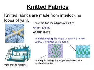
Background: Fat-Tree • Inter-connect racks (of servers) using a fat-tree topology • Fat-Tree: a special type of Clos Networks (after C. Clos) K-ary fat tree: three-layer topology (edge, aggregation and core) • each pod consists of (k/2)2 servers & 2 layers of k/2 k-port switches • each edge switch connects to k/2 servers & k/2 aggr. switches • each aggr. switch connects to k/2 edge & k/2 core switches • (k/2)2 core switches: each connects to k pods Fat-tree with K=2
Why? • Why Fat-Tree? • Fat tree has identical bandwidth at any bisections • Each layer has the same aggregated bandwidth • Can be built using cheap devices with uniform capacity • Each port supports same speed as end host • All devices can transmit at line speed if packets are distributed uniform along available paths • Great scalability: k-port switch supports k3/4 servers Fat tree network with K = 3 supporting 54 hosts
PortLand Assuming: a Fat-tree network topology for DC • Introduce “pseudo MAC addresses” to balance the pros and cons of flat- vs. topology-dependent addressing • PMACs are “topology-dependent,” hierarchical addresses • But used only as “host locators,” not “host identities” • IP addresses used as “host identities” (for compatibility w/ apps) • Pros: small switch state & Seamless VM migration • Pros: “eliminate” flooding in both data & control planes • But requires a IP-to-PMAC mapping and name resolution • a location directory service • And location discovery protocol & fabric manager • for support of “plug-&-play”
PMAC Addressing Scheme • PMAC (48 bits): pod.position.port.vmid • Pod: 16 bits; position and port (8 bits); vmid: 16 bits • Assign only to servers (end-hosts) – by switches pod position
Location Discovery Protocol • Location Discovery Messages (LDMs) exchanged between neighboring switches • Switches self-discover location on boot up Location Characteristics Technique Tree-level (edge, aggr. , core) auto-discovery via neighbor connectivity Position # aggregation switch help edge switches decide Pod # request (by pos. 0 switch only) to fabric manager
PortLand: Name Resolution • Edge switch listens to end hosts, and discover new source MACs • Installs <IP, PMAC> mappings, and informs fabric manager
PortLand: Name Resolution … • Edge switch intercepts ARP messages from end hosts • send request to fabric manager, which replies with PMAC
PortLand: Fabric Manager • fabric manager: logically centralized, multi-homed server • maintains topology and <IP,PMAC> mappings in “soft state”
Loop-free Forwarding and Fault-Tolerant Routing • Switches build forwarding tables based on their position • edge, aggregation and core switches • Use strict “up-down semantics” to ensure loop-free forwarding • Load-balancing: use any ECMP path via flow hashing to ensure packet ordering • Fault-tolerant routing: • Mostly concerned with detecting failures • Fabric manager maintains logical fault matrix with per-link connectivity info; inform affected switches • Affected switches re-compute forwarding tables
Current solutions for increasing data center network bandwidth FatTree BCube 1. Hard to construct 2. Hard to expand
An alternative: hybrid packet/circuit switched data center network • Goal of this work: • Feasibility: software design that enables efficient use of optical circuits • Applicability: application performance over a hybrid network
Optical circuit switching v.s. Electrical packet switching 16x40Gbps at high end e.g. Cisco CRS-1 320x100Gbps on market, e.g. CalientFiberConnect Packet granularity Less than 10ms e.g. MEMS optical switch
Optical circuit switching is promising despite slow switching time • [IMC09][HotNets09]: “Only a few ToRs are hot and most their traffic goes to a few other ToRs. …” • [WREN09]: “…we find that traffic at the five edge switches exhibit an ON/OFF pattern… ” Full bisection bandwidth at packet granularity may not be necessary
Optical paths are provisioned rack-to-rack • A simple and cost-effective choice • Aggregate traffic on per-rack basis to better utilize optical circuits Hybrid packet/circuit switched network architecture Electrical packet-switched network for low latency delivery Optical circuit-switched network for high capacity transfer
Design requirements Traffic demands • Control plane: • Traffic demand estimation • Optical circuit configuration • Data plane: • Dynamic traffic de-multiplexing • Optimizing circuit utilization (optional)
c-Through (a specific design) No modification to applications and switches Leverage end-hosts for traffic management Centralized control for circuit configuration
c-Through - traffic demand estimation and traffic batching Per-rack traffic demand vector Applications 1. Transparent to applications. Socket buffers 2. Packets are buffered per-flow to avoid HOL blocking. • Accomplish two requirements: • Traffic demand estimation • Pre-batch data to improve optical circuit utilization
c-Through - optical circuit configuration configuration Traffic demand Controller configuration Use Edmonds’ algorithm to compute optimal configuration Many ways to reduce the control traffic overhead
c-Through - traffic de-multiplexing VLAN #1 • VLAN-based network isolation: • No need to modify switches • Avoid the instability caused by circuit reconfiguration VLAN #2 circuit configuration traffic • Traffic control on hosts: • Controller informs hosts about the circuit configuration • End-hosts tag packets accordingly Traffic de-multiplexer VLAN #1 VLAN #2
FAT-Tree: Special Routing • Enforce a special (IP) addressing scheme in DC • unused.PodNumber.switchnumber.Endhost • Allows host attached to same switch to route only through switch • Allows inter-pod traffic to stay within pod • Use two level look-ups to distribute traffic and maintain packet ordering • First level is prefix lookup • used to route down the topology to servers • Second level is a suffix lookup • used to route up towards core • maintain packet ordering by using same ports for same server