CHAPTER OBJECTIVES
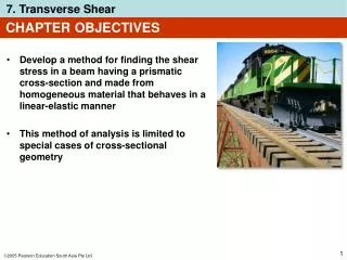
CHAPTER OBJECTIVES. Develop a method for finding the shear stress in a beam having a prismatic x-section and made from homogeneous material that behaves in a linear-elastic manner This method of analysis is limited to special cases of x-sectional geometry .

CHAPTER OBJECTIVES
E N D
Presentation Transcript
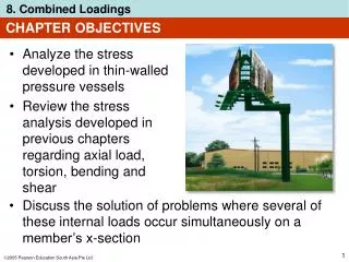
CHAPTER OBJECTIVES • Develop a method for finding the shear stress in a beam having a prismatic x-section and made from homogeneous material that behaves in a linear-elastic manner • This method of analysis is limited to special cases of x-sectional geometry • Discuss the concept of shear flow, with shear stress for beams and thin-walled members • Discuss the shear center
CHAPTER OUTLINE • Shear in Straight Members • The Shear Formula • Shear Stresses in Beams • Shear Flow in Built-up Members • Shear Flow in Thin-Walled Members • *Shear Center
7.1 SHEAR IN STRAIGHT MEMBERS • Shear V is the result of a transverse shear-stress distribution that acts over the beam’s x-section. • Due to complementary property of shear, associated longitudinal shear stresses also act along longitudinal planes of beam
7.1 SHEAR IN STRAIGHT MEMBERS • As shown below, if top and bottom surfaces of each board are smooth and not bonded together, then application of load P will cause the boards to slide relative to one another. • However, if boards are bonded together, longitudinal shear stresses will develop and distort x-section in a complex manner
7.1 SHEAR IN STRAIGHT MEMBERS • As shown, when shear V is applied, the non-uniform shear-strain distribution over x-section will cause it to warp, i.e., not remain in plane.
7.1 SHEAR IN STRAIGHT MEMBERS • Recall that the flexure formula assumes that x-sections must remain plane and perpendicular to longitudinal axis of beam after deformation • This is violated when beam is subjected to both bending and shear, we assume that the warping is so small it can be neglected. This is true for a slender beam (small depth compared with its length) • For transverse shear, shear-strain distribution throughout the depth of a beam cannot be easily expressed mathematically
7.1 SHEAR IN STRAIGHT MEMBERS • Thus, we need to develop the formula for shear stress is indirectly using the flexure formula and relationship between moment and shear (V = dM/dx)
VQ It = 7.2 THE SHEAR FORMULA • By first principles, flexure formula and V = dM/dx, we obtain Equation 7-3 = shear stress in member at the pt located a distance y’ from the neutral axis. Assumed to be constant and therefore averaged across the width t of member V = internal resultant shear force, determined from method of sections and equations of equilibrium
VQ It = Q =∫A’ydA’ = y’A’, where A’ is the top (or bottom) portion of member’s x-sectional area, defined from section where t is measured, and y’ is distance of centroid of A’, measured from neutral axis 7.2 THE SHEAR FORMULA • By first principles, flexure formula and V = dM/dx, we get: Equation 7-3 I = moment of inertia of entire x-sectional area computed about the neutral axis t = width of the member’s x-sectional area, measured at the pt where is to be determined
7.2 THE SHEAR FORMULA • The equation derived is called the shear formula • Since Eqn 7-3 is derived indirectly from the flexure formula, the material must behave in a linear-elastic manner and have a modulus of elasticity that is the same in tension and in compression • Shear stress in composite members can also be obtained using the shear formula • To do so, compute Q and I from the transformed section of the member as discussed in section 6.6. Thickness t in formula remains the actual width t of x-section at the pt where is to be calculated
h2 4 1 2 ( ) Q = y2 b 7.3 SHEAR STRESSES IN BEAMS Rectangular x-section • Consider beam to have rectangular x-section of width b and height h as shown. • Distribution of shear stress throughout x-section can be determined by computing shear stress at arbitrary height y from neutral axis, and plotting the function. Hence,
6V bh3 ( ) = y2 h2 4 7.3 SHEAR STRESSES IN BEAMS Rectangular x-section • After deriving Q and applying the shear formula, we have Equation 7-4 • Eqn 7-4 indicates that shear-stress distribution over x-section is parabolic.
V A max = 1.5 7.3 SHEAR STRESSES IN BEAMS Rectangular x-section • At y = 0, we have Equation 7-5 • By comparison,max is 50% greater than the average shear stress determined from avg = V/A.
7.3 SHEAR STRESSES IN BEAMS Wide-flange beam • A wide-flange beam consists of two (wide) “flanges” and a “web”. • Using analysis similar to a rectangular x-section, the shear stress distribution acting over x-section is shown
7.3 SHEAR STRESSES IN BEAMS Wide-flange beam • The shear-stress distribution also varies parabolically over beam’s depth • Note there is a jump in shear stress at the flange-web junction since x-sectional thickness changes at this pt • The web carries significantly more shear force than the flanges
7.3 SHEAR STRESSES IN BEAMS Limitations on use of shear formula • One major assumption in the development of the shear formula is that shear stress is uniformly distributed over width t at section where shear stress is to be determined • By comparison with exact mathematical analysis based on theory of elasticity, the magnitude difference can reach 40% • This is especially so for the flange of a wide-flange beam
7.3 SHEAR STRESSES IN BEAMS Limitations on use of shear formula • The shear formula will also give inaccurate results for the shear stress at the flange-web junction of a wide-flange beam, since this is a pt of sudden x-sectional change (stress concentration occurs here) • Furthermore, inner regions of flanges are free boundaries, thus shear stress at these boundaries should be zero • However, shear formula calculated at these pts will not be zero
7.3 SHEAR STRESSES IN BEAMS Limitations on use of shear formula • Fortunately, engineers are often interested in the average maximum shear stress, which occurs at the neutral axis, where b/h ratio is very small • Also, shear formula does not give accurate results when applied to members having x-sections that are short or flat, or at pts where the x-section suddenly changes • It should also not be applied across a section that intersects the boundary of a member at an angle other than 90o
7.3 SHEAR STRESSES IN BEAMS IMPORTANT • Shear forces in beams cause non-linear shear-strain distributions over the x-section, causing it to warp • Due to complementary property of shear stress, the shear stress developed in a beam acts on both the x-section and on longitudinal planes • The shear formula was derived by considering horizontal force equilibrium of longitudinal shear stress and bending-stress distributions acting on a portion of a differential segment of the beam
7.3 SHEAR STRESSES IN BEAMS IMPORTANT • The shear formula is to be used on straight prismatic members made of homogeneous material that has linear-elastic behavior. Also, internal resultant shear force must be directed along an axis of symmetry for x-sectional area • For beam having rectangular x-section, shear stress varies parabolically with depth. • For beam having rectangular x-section, maximum shear stress is along neutral axis
7.3 SHEAR STRESSES IN BEAMS IMPORTANT • Shear formula should not be used to determine shear stress on x-sections that are short or flat, or at pts of sudden x-sectional changes, or at a pt on an inclined boundary
7.3 SHEAR STRESSES IN BEAMS Procedure for analysis Internal shear • Section member perpendicular to its axis at the pt where shear stress is to be determined • Obtain internal shear V at the section Section properties • Determine location of neutral axis, and determine the moment of inertia I of entire x-sectional area about the neutral axis • Pass an imaginary horizontal section through the pt where the shear stress is to be determined
7.3 SHEAR STRESSES IN BEAMS Procedure for analysis Section properties • Measure the width t of the area at this section • Portion of area lying either above or below this section is A’. • Determine Q either by integration, Q = ∫A’y dA’, or by using Q = y’A’. • Here,y’is the distance of centroid ofA’, measured from the neutral axis. (TIP:A’ is the portion of the member’s x-sectional area being “held onto the member” by the longitudinal shear stresses.)
7.3 SHEAR STRESSES IN BEAMS Procedure for analysis Shear stress • Using consistent set of units, substitute data into the shear formula and compute shear stress • Suggest that proper direction of transverse shear stress be established on a volume element of material located at the pt where it is computed • acts on the x-section in the same direction as V. From this, corresponding shear stresses acting on the three other planes of element can be established
EXAMPLE 7.3 Beam shown is made from two boards. Determine the maximum shear stress in the glue necessary to hold the boards together along the seams where they are joined. Supports at B and C exert only vertical reactions on the beam.
EXAMPLE 7.3 (SOLN) Internal shear Support reactions and shear diagram for beam are shown below. Maximum shear in the beam is 19.5 kN.
yA A y = = ... = 0.120 m EXAMPLE 7.3 (SOLN) Section properties The centroid and therefore the neutral axis will be determined from the reference axis placed at bottom of the x-sectional area. Working in units of meters, we have Thus, the moment of inertia, computed about the neutral axis is, I = ... = 27.0(10-6) m4
EXAMPLE 7.3 (SOLN) Section properties The top board (flange) is being held onto the bottom board (web) by the glue, which is applied over the thickness t = 0.03m. Consequently A’ is defined as the area of the top board, we have Q = y’A’ = [(0.180 m 0.015 m 0.120 m] (0.03 m)(0.150 m) Q = 0.2025(10-3) m3
VQ It EXAMPLE 7.3 (SOLN) Shear stress Using above data, and applying shear formula yields max = = ... = 4.88 MPa Shear stress acting at top of bottom board is shown here. It is the glue’s resistance to this lateral or horizontal shear stress that is necessary to hold the boards from slipping at support C.