Download
1 / 46
630 likes | 1.49k Vues
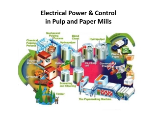
Electrical Power & Control in Pulp and Paper Mills. Electrical Power & Control in Pulp and Paper Mills. Electrical Power & Control in Pulp and Paper Mills. Distribution & utilization voltage levels HV – 115kV, 230kV MV – 15kV, 5kV, 2.4kV LV – 480V, 600V, 277V Misc. loads – 120V, 240V

E N D
Electrical Power & Control in Pulp and Paper Mills Distribution & utilization voltage levels HV – 115kV, 230kV MV – 15kV, 5kV, 2.4kV LV – 480V, 600V, 277V Misc. loads – 120V, 240V Control – various voltages (120VAC, 125VDC, 48VDC, 24VDC, 12VDC)
Electrical Power & Control in Pulp and Paper Mills Utility supply Single or multiple incoming line sources. Generation Co-generation typical for large steam use. Process steam from generator turbine extraction. Synchronous machines help with PF correction. (utility penalty for low PF)
Plant W 13.8kV, 2,400V, and 480V distribution 160 distribution transformers – 20 MV (2,400V) and 140 LV (480V) 1 generator – 42MW @ 13.8kV Three 15kV reactors (2MVA, 6MVA, &9MVA) 160MW total connected motor load 95MW motor load @ 2,300V 65MW motor load @ 460V 2 utility ties – 50MVA@230kV and 125MVA@230kV 2,700+ buses 250+ protective relays
Plant P 13.8kV, 4,160V, and 480V distribution 110 distribution transformers – 20 MV (4,160V) and 90 LV (480V) 4 generators – sizes 10MW up to 48MW Two 15kV reactors (4MVA & 7MVA) 140MW connected motor load 95MW motor load @4000V 45MW motor load @460V 2 utility ties – 40MVA@115kV and 27MVA@230kV 1,100+ buses 500+ protective relays
Control Systems • Process Control Terminology • Basic Instrument Selection Considerations • Variables: • Pressure, Level, Temperature, Flow, Position, Velocity • DCS/PLC Systems, now called PCS, • (Process Control Systems) • Control Loop Variability & Tuning • Alarm Management • Advanced Process Controls • Interlocking
What is Process Control? • Measurement & instrumentation (transmitters, sensors, analyzers) • Controllers and control systems (DCS, PLC, local controllers) • Final control elements (control valves, dampers, VF drives) • Process control may be implemented by use of “hard wiring”, PLC systems, DCS systems, APC systems, wired and wireless networks, and by combinations of other measurement and control devices.
DCS Systems Advantages of today’s DCS systems (recent vintage) : • Lower initial equipment cost. • Standard hardware & software – MS Windows & IBM compatible. • More powerful controllers (faster, more memory, better diagnostics, more execution space available). • Communicate using standard interfaces : • Ethernet, DeviceNet, ControlNet, Profibus. • Update of hardware costs much less than older proprietary systems - can be updated almost indefinitely (virtual servers, thin clients, etc.). • Provides easy data access for advanced applications.
DCS Systems Disadvantages of today’s DCS • Open systems design requires frequent OS updating. • Susceptible to virus infiltration and malicious attacks. • Correct versions of software required for compatibility. • Flexibility of systems makes everyone want something different. • Contract update service may be needed to deal with issue of frequent software updates. • Need to consider cyber security. Only limited access to the process servers should be allowed, but business divisions think they must control the plant network.
DCS Systems • Strengths of DCS Systems • Handles both analog and discrete I/O well • Handles I/O interfaced via communication links well • Operator interfaces are well developed. • Integrated alarming and interlock functions can be customized as needed. • Great selection of control algorithms. • Control loop tuning applications available. • Control loop monitoring applications available. • Supports advanced control applications. • Direct HART compatibility with smart field devices. • Direct bus compatibility with MCCs and adjustable speed drives.
DCS or PLC? (differences are minimal, new term PCS) • Use PLC for small specialized discrete control tasks. • Almost exclusively discrete I/O and logic. • Minimal data reporting required. • Suitable for dedicated safety systems (BMS, other SIS). • Insist on using PLCs that are “plant standard”. • Still consider DCS if existing DCS in continuous process area. • PLC better for servo motor controls, vector control, positioning, etc. • Specialized PLC for SIS (Safety Instrumented Systems). • Safety rated requirement per ANSI/ISA S.84, IEC, etc. • Dual (or triple) redundancy, depending on criticality.
Advanced Process Controls • Why APC? • Automates control of overall area processes. • Provides continuous control over existing manual changes. • Can provide consistent control “at least” as good as the best operator. (on all loops at the same time) • Optimize savings in energy, chemicals and raw materials. • Improve product quality and reduce variability. • Limit operations to safe and environmentally acceptable regions. • Very short payback.
Advanced Process Controls Why not APC? • Cannot sustain savings long term if not applied correctly • Base process loops need to be tuned and operating correctly. (Only partial APC benefit can be realized with poorly maintained and tuned instrumentation.) • Correct program for application must be selected • Proper engineering procedures must be applied • Support program must be in place to sustain savings • Online monitoring by APC supplier must be included • Usage must be monitored by management and reported • Otherwise, investment is lost when program is abandoned
HART vs. Foundation Fieldbus protocols? • HART preserves the 4-20mA current loop, and adds digital information on top of this existing signal component. • Foundation Fieldbus extends control system architecture to the field device, via multi-drop bus configuration. • HART integrates easier than Fieldbus with existing, older systems. • Potential for precision tuning and accuracy of a control loop is greater for Fieldbus. • Electrically, robust signal is better with Fieldbus. • Discussion and comparison of these two protocols is likely to persist for a long time.
Motor Control via DCS or PLC • Device-Net or Profi-Bus networks today. • Ability to add (or troubleshoot) individual motor starters. • Single network to MCC lineup eliminates discrete I/O control wiring. • Diagnostic data is provided from smart starters to DCS. • Enables quick checkout, commissioning, and startup. • AF Drives and Motor Overload Modules included in network. • Other networks available. • Ethernet networks will become more prevalent very soon. • Wireless is gaining popularity for remote applications and mobile vehicles (manned, or unmanned). • Fiber optic links also available for drives and remote I/O.
Alarm Management ANSI/ISA Standard 18.2-2009 - identifies alarm management lifecycle philosophy including: • Identification • Rationalization • Detailed Design • Implementation • Operation • Maintenance • Management Of Change (MOC) • Monitoring and Assessment • Audit
Interlocking • Interlocking is different from alarming. • Primarily used to prevent EH&S incidents - “Safety interlocks” and to prevent equipment damage • “Safety Interlocks” should always be “hardwired” or securely transferred • By-passing safety interlocks SHALL BEdocumented by SOPs and approved by management • Interlocks are also used to prevent operational events that could cause spills, flooding, plugging, trips and other inconveniences. • Interlocks can also be used to automate Operator functions to allow him/her to concentrate on more important tasks • Typical uses for conventional interlocks • Starting consistency transmitters, vacuum pumps, oil pumps, etc.. when the main drive starts • Shutting down vacuum pumps (or refiners), on loss of fluid to the mechanical seals • Shutting the equipment down preceding the failed piece in the sequential operation • Automatically initiate FLUSH upon shut-down (intentional, or unintentional) • Group, or one button starts, like vacuum system, feed system, showers, press, batch digester, screen system, etc….
Questions? Thank you for your attention!