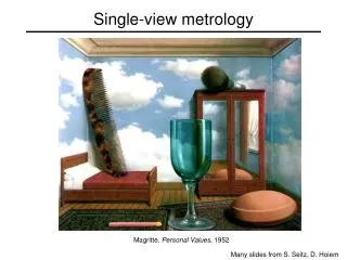
Recovering 3D Structure from Single-View Geometry
This document explores the intricacies of recovering 3D structure from single-view imagery, focusing on the inherent ambiguities of 3D reconstruction. Utilizing concepts from multi-view geometry and the pinhole camera model, we discuss pivotal camera parameters such as the principal point, focal length, and pixel magnification factors. The challenges of camera calibration, particularly with respect to intrinsic and extrinsic parameters, are addressed, including the importance of correspondence between 2D and 3D points and methodologies for optimizing reconstructed structures.


Recovering 3D Structure from Single-View Geometry
E N D
Presentation Transcript
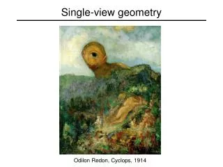
Single-view geometry Odilon Redon, Cyclops, 1914
X? X? X? Our goal: Recovery of 3D structure • Recovery of structure from one image is inherently ambiguous x
Our goal: Recovery of 3D structure • Recovery of structure from one image is inherently ambiguous
Our goal: Recovery of 3D structure • Recovery of structure from one image is inherently ambiguous
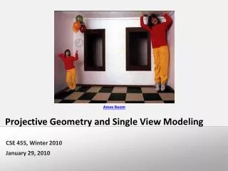
Ames Room http://en.wikipedia.org/wiki/Ames_room
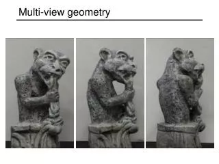
Our goal: Recovery of 3D structure • We will need multi-view geometry
Recall: Pinhole camera model • Principal axis: line from the camera center perpendicular to the image plane • Normalized (camera) coordinate system: camera center is at the origin and the principal axis is the z-axis
Principal point • Principal point (p): point where principal axis intersects the image plane • Normalized coordinate system: origin of the image is at the principal point • Image coordinate system: origin is in the corner • How to go from normalized coordinate system to image coordinate system? py px
Principal point offset principal point: py px
Principal point offset principal point: calibration matrix
Pixel coordinates • mx pixels per meter in horizontal direction, my pixels per meter in vertical direction Pixel size: m pixels pixels/m
Camera rotation and translation • In general, the camera coordinate frame will be related to the world coordinate frame by a rotation and a translation • Conversion from world to camera coordinate system (in non-homogeneous coordinates): coords. of point in camera frame coords. of camera center in world frame coords. of a pointin world frame
Camera rotation and translation Note: C is the null space of the camera projection matrix (PC=0)
Camera parameters • Intrinsic parameters • Principal point coordinates • Focal length • Pixel magnification factors • Skew (non-rectangular pixels) • Radial distortion
Camera parameters • Intrinsic parameters • Principal point coordinates • Focal length • Pixel magnification factors • Skew (non-rectangular pixels) • Radial distortion • Extrinsic parameters • Rotation and translation relative to world coordinate system
Xi xi Camera calibration • Given n points with known 3D coordinates Xi and known image projections xi, estimate the camera parameters
Camera calibration: Linear method Two linearly independent equations
Camera calibration: Linear method • P has 11 degrees of freedom • One 2D/3D correspondence gives us two linearly independent equations • Homogeneous least squares: find p minimizing ||Ap||2 • Solution given by eigenvector of ATA with smallest eigenvalue • 6 correspondences needed for a minimal solution
Camera calibration: Linear method • Note: for coplanar points that satisfy ΠTX=0,we will get degenerate solutions (Π,0,0), (0,Π,0), or (0,0,Π)
Camera calibration: Linear method • Advantages: easy to formulate and solve • Disadvantages • Doesn’t directly tell you camera parameters • Doesn’t model radial distortion • Can’t impose constraints, such as known focal length and orthogonality • Non-linear methods are preferred • Define error as squared distance between projected points and measured points • Minimize error using Newton’s method or other non-linear optimization