Leica Photogrammetry Suite
601 likes | 1.45k Vues
Leica Photogrammetry Suite. LPS 2010 ERDAS. LPS Introduction. Digital photogrammetry program that allows for triangulation and orthorectification of images from various cameras and satellites. Geometric Distortions. Raw imagery has geometric distortions Distortion from

Leica Photogrammetry Suite
E N D
Presentation Transcript
Leica Photogrammetry Suite LPS 2010 ERDAS
LPS Introduction • Digital photogrammetry program that allows for • triangulation and • orthorectification of images from various cameras and satellites
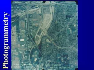
Geometric Distortions • Raw imagery has geometric distortions • Distortion from • Camera and sensor orientation • Terrain relief • Earth curvature • Scanning distortion • Measurement errors • Thus, raw imagery cannot be used as a planimetric map
Orthorectification • Raw images need to be rectified in order to be used for geospatial information • Ortho photos are the leading source for geospatial data. • Goal of orthorectification-- make images planimetrically correct. i.e., constant scale or like a map. • STEPS in LPS…similar to CLASS work
The Major Steps in Digital Orthorectification
In the LPS labs you will…. Create a new project Add imagery to the block file Define the camera model Measure the GCPs and Check points Use the automatic tie point collection Triangulate the images Orthorectify the images Use orthoimages to create geospatial data
EndGoal • Orthorectified images of campus. • Use ortho images to create geospatial data that will be dropped into ArcGIS. • Understand how the concepts you are learning in class are utilized in a industry standard software package!
LPS Manual – We are going to start with Frame Camera Tour This can be found w:\\farm\cce\fall2012\cce201-011\public_html\Photgrammetry
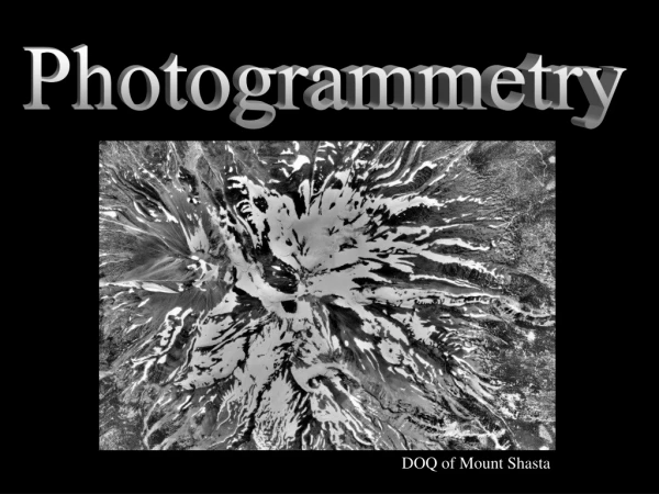
LPS – Orthorectification • Imagery sources that can be rectified • Aerial Photography • Satellite imagery • Digital and video camera • Satellite imagery – panchromatic or multispectral • Landsat • SPOT Image • GeoEye
Extracting Digital Terrain Models (DTM) • Automatic terrain extraction (elevations) • DEM: digital elevation models • TIN: triangular irregular networks • 3D Shape files (ESRI)
Other Features • Ortho Resampling – change cell size • Ortho Mosaicking – merge images • Feature Collection – collect GIS data
OSU Imagery • Flown September 1, 2007 • Scale of printed photos 1”= 400’ • Scanning Resolution: 25 micron dpi • Ground coverage: one pixel is xx feet on ground (0.01 m or 0.0328 ft) • Flying Height: 850.4 meters or 2790 feet • Names of Photos: • 1_4.tif • 1_5.tif
Lab 1 • Map Drive to FARM Step1 Step3 Step2 Step4
Map Drive to FARM and Short Cut • \\farm.cce.oregonstate.edu\cce_classes\ce561\yourname • Right click their folder=>Send To=>Desktop (this creates a shortcut). • That way if they reset their profile over the course of the quarter, they still have a way to find it. • Mapped drives always get lost upon profile resets. Right-click your folder name with mouse—Send to Desktop Create Short Cut
Step 1: Copy and Review data • Go to classes and COPY folder “Photos” • You do NOT have write privileges on CLASSES • W:\cce\fall2012\cce201-001\public_html\Photogrammetry\PHOTOS • PASTE to \\farm.cce.oregonstate.edu\cce_classes\ce561\yourname
Review Photos in PAINT • Open Paint and review each photo • What is the smallest object you can discern? • Can you estimate the cell size or resolution of the photo? • Go to fiducialsand mark down numbers and location
Step 2: LPS- New Project and Camera • Create new project • Add imagery to block file • Define camera model • In the LPS Manual – we will start with the Tutorial: Frame Camera Tour Guide. • LPS page 77 • PDF page 99
Review – Interior Orientation • Interior orientation defines the internal geometry of camera as it existed at the time of image capture • Image positions of fiducials marks --referenced to a pixel.
Step 3: Exterior Orientation • Defines the relationship between ground space coordinate system (X,Y,Z) and the image space coordinate system (x,y,z) • Three rotation angles are commonly used to define angular orientation • Omega (ω) • Phi (φ) • Kappa (ĸ)
Elements of Exterior Orientation x, y, z - image X, Y, Z - ground
Collinearity Condition • Specifies that the exposure station, ground point, and corresponding image point must ALL lie along a straight line, there by being collinear. • Two equations comprise the collinearity condition • This defines relationship between: camera, image and ground
Space Forward Intersection • Determines ground coordinates in overlapping areas of two or more images. • Collinearity condition enforced – stating that the light rays from the same points on the images intersect at same ground point.
Lab2 – Exterior Orientation • Enter ground control …s/b well-defined, dispersed, and permanent. • Utility infrastructure – manholes, fire hydrants • Benchmarks • Corner of sidewalks • Intersection of roads – fuzzy • Minimum of 3 GPS – but really much more. You have 10 GCPs use 8 only.
Lab 3 – Exterior Orientation • Enter GCPs – • Locate GCPs on image and then enter N/E (8 each) • Save 2 to use as check points (additional GCPs) • Entered same way as GCPs • Used to verify the accuracy of triangulation • Perform automatic tie point generation • Perform aerial triangulation • Check and SAVE the results
Check the Results and SAVE • Output – standard error of last iteration is most important • Review Exterior Orientation parameters for each image: Omega, Phi, Kappa • Note the residuals of control points and check points
Lab 2 – Notes on entering GCPs • Start on Page 99 in LPS 1. Convert GCPs to NAD83 feet and NAVD88 feet • divide GCPS by 0.3048 to convert meters to feet 2. Locate GCP on image and enter NEZ in feet 3. Locate same GCP on adjacent image 4. Repeat for all of GCPs except for last two
LAB 3 - Orthophotos Review: past labs Pyramids Interior Orientation Exterior Orientation This lab – create orthophotos
Ortho Resampling 1. DEM – Provides elevations For every image pixel 2. Images need to line Up with spatial Referencing of DEM DEM- Lidar 2010, from State of Oregon - DOGAMI, 3ft horizontal resolution, vertical resolution typically ~ 4-8 inches Vertical units (elevation) – feet 3. Output cell size are image: Related to scale and scanning resolution Our images – 1” = 400’ and 25 microns…you can determine cell size
Scanning Resolution Our images are 1” = 400 ft and 25 microns
Resampling – Nearest Neighbor N.N. – looks only at closest pixels Map Projection – already set SPCS, WGS 84, NAD83 Feet
Orthophotos Click on Control point and see residuals