Exploring Photogrammetry: A Comprehensive Study of Mount Shasta
This document provides an in-depth exploration of photogrammetry, emphasizing both analog and digital methods used in aerial photography to make precise measurements. It details the process of capturing aerial images, ensuring appropriate overlaps, calculating photo scales, and using fiducial marks for accurate measurements. The study also discusses potential applications such as creating orthophotos and digital elevation models, highlighting techniques for measuring object heights, areas, and perimeters. The objective is to shed light on the importance of photogrammetry in mapping and understanding geographical features, specifically Mount Shasta.

Exploring Photogrammetry: A Comprehensive Study of Mount Shasta
E N D
Presentation Transcript
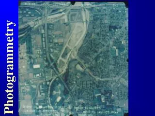
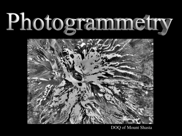
Photogrammetry DOQ of Mount Shasta
Introduction • Photogrammetry is … • “the art and science of making accurate measurements by means of aerial photography” (Jensen 2000) • Analog photogrammetry • performed visually using hard-copy data • Digital photogrammetry • computer-aided using digitized data
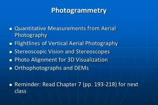
Some Potential Measurements • Analog photogrammetry of single vertical air photo • Photo scale • Object height, length, area, perimeter • Grayscale tone/color • Analog photogrammetry of stereoscopic air photos • All of the above • Precise planimetric (x, y) object location and height (z) • Digital photogrammetry of stereoscopic air photos • All of the above • Orthophotos • Digital elevation models (DEMs) • Bathymetric models
Flight Lines/ Strips of Vertical AP • Flight line • “Flight path” along which photos were acquired at specific exposure stations • (Nadir line: Flight line-equivalent on the ground, directly beneath the aircraft, during photo acquisition) • Intervalometer • Determines time b/w individual exposures • Setting depends on desired photo scale and aircraft speed • Stereoscopic overlap/endlap (~ 60%) • Sidelap (~ 20-30%) • Block of air photos: multiple flightlines with sidelap
Flight Lines/ Strips of Vertical AP Flight line Photo #1 Photo #2 Photo #3 60% overlap
Flight line #1 Flight line #2 Flight line #3 60% overlap Flight Lines/ Strips of Vertical AP Block of AP 20-30% sidelap
Flight line #3 Flight line #4 Flight Lines/ Strips of Vertical AP Exposure #6 Exposure #4 Exposure #5 Exposure #4 Exposure #6 Exposure #5
Flight Lines/ Strips of Vertical AP • Uncontrolled Photomosaic • Compiled from previously shown block of air photos
Fiducial marks Date: 03-30-1993 Flight line # 04 Scale: 1”=500’ Photo# 05 Fiducial Marks • Fiducial marks • Small targets on camera body, whose positions relative to the camera body are calibrated • Define image coordinate system, whereby the projection center position is known • Vary with manufacturer
Principal point (PP) Principal Point (PP) • Principal point • On the ground: Location where the camera’s optical axis was pointing during exposure • On air photo: Intersection of lines b/w opposite fiducial marks
Conjugate Principal Point (CPP) • Conjugate principal point (CPP) • Location of PP on adjacent photographs (after transfer) Flight line PP3-4 PP3-5 CPP3-5 CPP3-4 60% Overlap
Conjugate Principal Point (CPP) • Note the 60% overlap area, which can be viewed stereoscopically • PP1 on Photo 1= CPP1 on Photo 2 • PP2 on Photo 2= CPP2 on Photo 1
Negative image space Optical axis Positive print +y +x Earth object space Sea level Vertical AP Geometry – Flat Terrain Negative image space (a’, b’, c’, d’) Reversal in tone and geometry the Earth Earth object space (A B, C, D) x, y = Photographic coordinate axes
Scale Measurement • Three ways to express scale of air photos • Verbal/ Written scale • Representative fraction (RF)/ Fractional scale • Graphic scale/ Scale bar
Scale Measurement • Single Air Photo Over Nearly Level Terrain • Two main methods • Compare size of (a) objects in real world or from map with (b) same objects on air photo • Compute relationship b/w camera focal length (ƒ) and altitude of aircraft AGL (H) Both equations yield representative fractions (dimensionless)!!! Distance from point a/A to b/B Scale proportional to f (image distance) Scale inversely proportional to H (object distance)
Vertical AP Geometry – Variable Terrain • Problem: • Many scales • Lower elevations • smaller scales • land “moved away” from camera • Higher elevations • larger scales • land “moved closer” toward camera
ab AB Scale Measurement • Single Air Photo Over Variable Terrain Lb Lo s = scale (representative fraction) h = terrain elevation ASL H = flight altitude ASL LP LB = Average/ Nominal Scale
Object Height Measurement • Two methods: • Image relief displacement • Shadow length
Height Measurement • Method 1: Image relief displacement • Vertical displacement of objects that are above (radial displacement away from PP) or below (radial displacement toward PP) the local datum • Amount of displacement, d, is: • directly proportional to the difference in elevation, h, between the top of the object and the local datum (the greater h, the greater d) • directly proportional to the radial distance, r, between the top of the displaced image and the PP (the greater r, the greater d) • inversely proportional to the altitude, H, of the camera above the local datum (the greater H, the smaller d)
Displacement d r b a H B Obj. h PP Local datum A Height Measurement • Method 1: Image relief displacement
Height Measurement • Method 1: Image relief displacement × Radial distance, r × Relief displacement, d
Height Measurement • Method 2: Shadow length a = Suns’s elevation angle h = object height L = Shadow length • Sun’s elevation angle, a: • Solar ephemeris table • Empirically for known object
Height Measurement • Method 2: Shadow length
Single vs. Multiple Air Photos • Single air photo • Shows objects from a specific vantage point at specific point in time • Multiple air photos • Show an object from a number of vantage points at different points in time, because the aircraft moves between exposures • In a succession of air photos, the position of a specific object will move from the left to the right (if the flight the line was from the left to the right)
Multiple Air Photos • Stereoscopic parallax • Change in position of an object with height, from one photo to the next relative to its background • Caused by aircraft’s motion
Parallax • Parallax • Apparent displacement in the position of an object, with respect to a frame of reference, caused by a shift in the position of observation Basis for stereoscopic viewing • Differential parallax • Differences in the parallax of various objects of interest • Basis for most planimetric (x, y) and topographic (x, y, z) maps
Fundamentals of Human Stereoscopy • Stereoscopy • Science of perceiving depth using two eyes • Binocular vision • Vision as a result of both eyes working as a team • Eye base/ Interpupillary distance • Distance between the eyes’ optical axes (63-69 mm) • Parallactic angle () • Angle formed by the two optical axes of the eyes as they converge on a point of interest • Decreases with increasing distance
Fundamentals of Human Stereoscopy • Depth perception • Result of changing parallactic angles with distance • Increases with increasing interpupillary distance • For distances up to 1,000 m • Hyperstereoscopy • Stereoscopic viewing in which the relief effect is noticeably exaggerated (e.g., by increasing interpupillary distance or extending the camera base)
Stereoscopy & Aerial Photography • 3D-viewing of terrain on air photos is possible, b/c: • Overlapping air photos contain stereoscopic parallax • Hyperstereoscopy allows us to view overlapping photos as if we were present at both exposure stations at the instant of exposure
Methods of Stereoscopic Viewing • Keeping the lines of sight parallel with the aid of a stereoscope • Keeping the lines of sight parallel without the aid of a stereoscope • Crossing the eyes and reversing the order of the stereoscopic images • Using anaglyphic or polarizing glasses
Stereoscopes • Stereoscope • Binocular viewing system initially developed for the analysis of terrestrial stereoscopic photos (mid-1800s) • Stereo World • Magazine published by the National Steroscopic Association (http://www.stereoview.org/stereoworld.html) • Stereoscopes for air photos • Same principles as used in original stereoscopes
Stereoscopes Terrestrial stereogram of the temple in Salt Lake City, UT (1899) (Source: Jensen 2000) Brewster’s lens stereoscope (1849) (Source: Jensen 2000) Vintage stereo camera (Source: Jensen 2000)
Pocket Lens Stereoscopes • “Handheld” • Two convex lenses mounted on metal/ plastic frame • Helps keep lines of view parallel • Magnifies the photography
Mirror Stereoscopes • Allows entire overlapping area of air photo stereo pair to be seen at once • Various magnification options
Stereoscopic Aerial Photography • Air base • Distance b/w two exposure stations • Becomes stretched eye base, which causes exaggerated third dimension when viewing stereoscopically • X-parallax • Change in object position from one photo to the next due to aircraft’s motion • Hypothetical example: • Objects A + B in the real world are recorded as points a + b in exposure L1 and a’ + b’ in exposure L2.
Stereoscopic Aerial Photography • Superposition • Vertical lines running through each of the photo’s PPs are superimposed on top one another • Parallax of point a: pa = xa – xa’ • Directly related to a point’s elevation above mean terrain • Greater for high elevations than low elevations Differential parallax • Example: Object A (the taller building) has greater x-parallax (pa) than Object B (pa)
Stereoscopic Aerial Photography Differences in the parallax between any two points facilitates the determination of elevation differences using stereoscopic parallax equations • A = arbitrary point at a lower elevation • B = arbitrary point at a higher elevation • a1, b1 = points "A" and "B" as imaged on the left image • a2, b2 = points "A" and "B" as imaged on the right image • Xa = ground X-parallax b/c the elevation of point "A" is above the reference plane • Xb = ground X-parallax b/c the elevation of point "B" is above the reference plane • ha = height of point "A" above the reference plane • hb = height of point "B" above the reference plane • Source: Natural Resources Canada (2004). http://www.ccrs.nrcan.gc.ca/ccrs/learn/tutorials/stereosc/chap4/chapter4_3_e.html.
Measurement of Parallax • Parallax Equation ho = Object height H-h = Altitude of aircraft above-ground-level (AGL) P = absolute stereoscopic parallax at the base of the object of interest dp = differential parallax • Equation yields correct only if: • Vertical air photos have 3º • Adjacent photos are exposed from approx. the same altitude AGL • The PPs of both photos are at approx. the same elevation AGL • The base of the objects of interest are at approx. the same elevation as that of the PPs
Measurement of Parallax • Parallax Equation • Requires three measurements on stereoscopic photos: • Determine altitude of aircraft AGL (H – h) • (Locate the principal point PP on each of the photos) • (Locate the conjugate principal point CPP on each of the photos) • (Position photographs along flight line by aligning PP and CPP of each photo ( Line of flight) • Determine the average photo air base (absolute stereoscopic parallax, P): • Measure distance between PP1 and CPP2 on Photo1 (= A-base1) • Measure distance between PP2 and CPP1 on Photo2 (= A-base2) • Mean of A-bases = average photo air base b/w two exposure stations = absolute stereoscopic parallax, P H – h P
A A CPP2 PP1 PP2 CPP1 B B A-base2 A-base1 Measurement of Parallax • Parallax Equation • Continued: • Measurement of absolute stereoscopic parallax, P • Absolute stereoscopic parallax, P = (A-base1 + A-base2)/2 L2 L1 Profile view of Photo 2 Profile view of Photo 1 P b’ o a b a’ o
Measurement of Parallax • Parallax Equation • Continued: • Measure the differential parallax, dp, between the location of the base and the location of the top of the building: • Ruler • Measurement using fiducial lines • Measurement based on superposition • Measurement using a parallax bar (stereometer) dp
xb’ A-base2 Fiducial line of Photo 1 Flight line PP1 CPP2 xb Fiducial line xa xa’ Measurement of Parallax • Parallax Equation • Continued: • Measurement of the differential parallax, dp, using fiducial lines • Photo 1 dp Plan view of Photo 1 Photo 1 y-axis x-axis b = base a = top
xb’ PP2 A-base2 Flight line xb’ CPP1 Fiducial line of Photo 2 xa’ xa’ Fiducial line Measurement of Parallax • Parallax Equation • Continued: • Measurement of the differential parallax, dp, using fiducial lines • Photo 2 dp Plan view of Photo 2 Photo 2 b’ a’
Measurement of Parallax • Parallax Equation • Continued: • Measurement of the differential parallax, dp, using fiducial lines • Example: • xa-parallax (top) on Photo 1: -3.82 in from the fiducial line • xb-parallax (base) on Photo 1: -3.606 in from the fiducial line • xa’-parallax (top) on Photo 2: -0.270 in from the fiducial line • xb’-parallax (top) on Photo 2: -0.267 in from the fiducial line • Absolute value of x-parallax of the top of the building:pa = |(-3.82 in)-(-0.270 in)| = 3.55 in • Absolute value of x-parallax of the base of the building:pb = |(-3.606 in)-(-0.267 in)| = 3.339 in • Differential parallax, dp = 3.55 – 3.339 = 0.211 in dp
Measurement of Parallax • Parallax Equation • Continued: • Measurement of the differential parallax, dp, using superposition • Align top and base of building parallel with the line of flight (distance b/w photos not important) • x-parallax of the top/ base of the building = Distance b/w the top/ base of the building on Photo 1 and the same top/ base corner of Photo 2 • Differential parallax, dp = |top-x-parallax – base-x-parallax| dp
Measurement of Parallax • Parallax Equation • Continued: • Measurement of the differential parallax, dp, using superposition dp pb pa
Measurement of Parallax • Parallax Equation • Continued: • Measurement of the differential parallax, dp, using a parallax bar (stereometer) • Parallax bar • Useful for deriving elevation changes and mapping contour lines dp
Area Measurement • Area measurement from unrectified air photos • Only if terrain is level (< 5% of flight altitude) or if the area is carefully stratified into zones of roughly the same scale (e.g., valleys, ridges) • Area measurement of well-known shapes • Measure, length, width, diameter, etc. and use straightforward mathematical relationships for circles (pr2), squares (s2), rectangles (lw), etc. • Area measurement of irregularly shaped polygons • Compensating polar planimeter • Dot grids • On-screen digitization
Area Measurement • Area measurement of irregularly shaped polygons • On-screen digitization 5-level land use map compiled from 1996 digital orthophotos. Source: Great Lakes Environmental Center 2003. www.glec-online.com