An Atmospheric Correction Algorithm for Hyperspectral Imagery
An Atmospheric Correction Algorithm for Hyperspectral Imagery. Ph.D. Dissertation Defense by: Lee C. Sanders Advisor: Dr. John R. Schott. Radiometry Overview Overview of atmospheric correction Elevation,column water vapor, and aerosol extraction methods: NLLSSF APDA RIMAC

An Atmospheric Correction Algorithm for Hyperspectral Imagery
E N D
Presentation Transcript
An Atmospheric CorrectionAlgorithm for HyperspectralImagery Ph.D. Dissertation Defense by: Lee C. Sanders Advisor: Dr. John R. Schott
Radiometry Overview Overview of atmospheric correction Elevation,column water vapor, and aerosol extraction methods: NLLSSF APDA RIMAC Inversion from sensor radiance to ground reflectance Contribution from the surround using the phase function Results Summary Outline
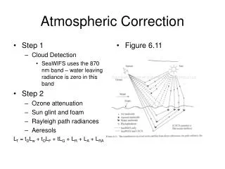
Radiative Transfer Paths Trapping Effect Environmental/Adjacency Effect
Radiative Transfer Paths Upwelled Radiance Downwelled Radiance
Radiative Transfer Paths Direct Solar
MODTRAN 4 Look-Up Table Surface Elevation Water Vapor Amount Visibility Channel # l Lgrnd Lu S Ld Lenv
Radiometry Overview Overview of atmospheric correction Elevation,column water vapor, and aerosol extraction methods: NLLSSF APDA RIMAC Inversion from sensor radiance to ground reflectance Contribution from the surround using the phase function Results Summary Outline
Make better quantitative estimates of absolute surface reflectances. Improve existing climatology models for weather forecasting. Monitor pollution. Determine how atmospheric chemistry impacts the trend of global warming. Why Atmospheric Correction?
Atmospheric Correction 1) Determine terrain elevation by surface pressure depth in 760nm oxygen band using NLLSSF. 2) Determine the visibility for a given aerosol type using a NLLSSF over the .4-.7µm range or use the RIMAC method from .55-.7µm range. 3) Determine atmospheric column water vapor content using the NLLSSF technique or the APDA technique on the .940µm absorption band. 4) From the calculated aerosol profile, determine the phase function-derived convolution kernel.
Radiometry Overview Overview of atmospheric correction Elevation,column water vapor, and aerosol extraction methods: NLLSSF APDA RIMAC Inversion from sensor radiance to ground reflectance Contribution from the surround using the phase function Results Summary Outline
Non-Linear Least-Squared Spectral Fit (NLLSSF) Technique Minimize the difference between the sensor radiance and the MODRAN-derived sensor radiance by changing parameters in the governing radiative transfer equation: LSE = Lsensor - ( LU + Lenv g +[Eocos()12+ Ld2 ]g/(1-Sg) ) g: Lambertian ground reflectance
.760µm Oxygen Band surface elevation .94µm H2O Band water vapor NLLSSF Flex Parameters .4-.70 µm Aerosol Band visibility
NLLSSF Model of Reflectance In the .760µm oxygen band, the target reflectance is assumed linear with = + In the case of the aerosol and water vapor bands the equation includes a non-linearity for liquid water : =++(H2Ol)
General Flow Chart of Algorithm Input Image Pixel: Solve for Surface Pressure Depth in .76µm O2 band. Input Constant Parameters (i.e geometry, particle density,etc) Solve for Atmospheric Visibility Given an Aerosol Type Using .4-7µm bands Solve for Total Column Water Vapor Using the .94µm band. Using all Solved Parameters, Invert Governing Radiometric Equation and Calculate Ground Reflectance.
The APDA (Atmospheric Pre-Corrected Differential Absorption) Technique A water vapor band depth ratio method that relates an Rapda value to a atmospheric columnar water vapor value.
The APDA Technique The single channel/band Rapda: which can be extended to more channels:
The APDA Technique Relate R ratio with the corresponding water vapor amount (PW) wv(PW) = RAPDA = e -(+(PW)) Solving for water vapor: -ln (RAPDA) - )1/ PW(RAPDA)= (
RIM depends on classification of homogenous areas with varying spectral contrasts. Band pair by band pair, the DCs for each class are regressed toward the origin and the intersections of all the classes are determined. Intersections below the “toe” of the histogram are discarded. The mean intersection becomes the estimate of total upwelling radiance. The Regression-Intersection Method for Aerosol Correction (RIMAC)
DCband2 class a class b DCu2 DCu1 DCband1 Regression Intersection Method (RIM)R.E. Crippen (1987) • Extrapolate data to intersection representing zero ground reflectance and upwelled radiance. • Intersections determined for many classes in each band pair.
Structural regression of bispectral classes. Classified Image Intersect class lines by extrapolation to zero reflectance point. Fit to MODTRAN LUT Extract spectral upwelled radiance from intersections’ averages. Regression Intersection Method for Aerosol Correction (RIMAC)
The total upwelled radiance is a combination of atmospheric upwelled scattered and environmental radiance. The average reflectance of the background is estimated either by Kaufman’s correlation with the 2.1µm band or by a simple linear fit to RIM total upwelled radiance estimate given an aerosol visibility. Finding Atmospheric Visibility
The visibility estimate is that which gives the minimum squared spectral radiance error compared to the RIM-derived total upwelled radiance. Finding Atmospheric Visibility MODTRAN- Derived
Radiometry Overview Overview of atmospheric correction Elevation,column water vapor, and aerosol extraction methods: APDA NLLSSF RIMAC Inversion from sensor radiance to ground reflectance Contribution from the surround using the phase function Results Summary Outline
First Pass Solve for Reflectance Once the atmospheric parameters have been set, the radiometric terms can be extracted from the MODTRAN 4 Look-Up Table and the sensor radiance can be inverted to ground reflectance for each pixel.
Second Pass Solve for Reflectance In the first pass, the surround reflectance was set to be equal to the target reflectance. To be rigorous, an approach had to be derived that estimated the aggregate reflectance contribution of the surround and the magnitude of the adjacency radiance.
Radiometry Overview Overview of atmospheric correction Elevation,column water vapor, and aerosol extraction methods: APDA NLLSSF RIMAC Inversion from sensor radiance to ground reflectance Contribution from the surround using the phase function Results Summary Outline
Light from the target surround is scattered into the sensor path The intensity distribution of radiance depends on the angle from sensor optical path and the aerosol phase function. The magnitude of the radiance depends on the target reflectance, the aerosol particle density, and the aerosol scattering cross-section. Environmental Contribution
Single Atmospheric Layer Diagram Scattering From Surround Into The Sensor Path Is Governed By The Aerosol Phase Function
Sensor IFOV of An Atmospheric Layer The scattering function for a unit layer is weighted by the solid angle subtended by the layer pixel at altitude h.
Atmospheric Layers 1 2 3 4 5 6
The scattering contributions are summed over all the atmospheric layers: Calculating Average Reflectance • For this algorithm, the real interest is the fractional reflectance contribution of each pixel in the surround:
Once a ravg map is created, the algorithm can proceed using the first pass atmospheric parameters as initial estimates. The atmospheric parameters are re-calculated using the same methodology as the first pass except a different radiative transfer equation is used. Final output is the reflectance map of the scene and the solved atmospheric parameters. Second Pass
Radiometry Overview Overview of atmospheric correction Elevation,column water vapor, and aerosol extraction methods: APDA NLLSSF RIMAC Inversion from sensor radiance to ground reflectance Contribution from the surround using the phase function Results Summary Outline