Download
1 / 12
170 likes | 324 Vues
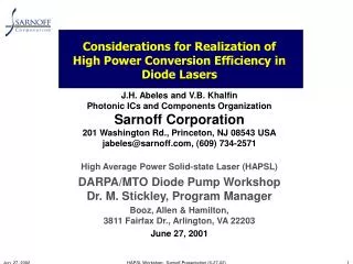
Considerations for Realization of High Power Conversion Efficiency in Diode Lasers. J.H. Abeles and V.B. Khalfin Photonic ICs and Components Organization Sarnoff Corporation 201 Washington Rd., Princeton, NJ 08543 USA jabeles@sarnoff.com, (609) 734-2571

E N D
Considerations for Realization of High Power Conversion Efficiency inDiode Lasers J.H. Abeles and V.B. KhalfinPhotonic ICs and Components OrganizationSarnoff Corporation201 Washington Rd., Princeton, NJ 08543 USAjabeles@sarnoff.com, (609) 734-2571 High Average Power Solid-state Laser (HAPSL) DARPA/MTO Diode Pump WorkshopDr. M. Stickley, Program Manager Booz, Allen & Hamilton, 3811 Fairfax Dr., Arlington, VA 22203 June 27, 2001 HAPSL Workshop: Sarnoff Presentation (6-27-02)
Lexicon • Power Conversion Efficiency • Potential Defect • Non-ohmic Resistance • Series Resistance = Ohmic Contact Resistance + Non-Ohmic Resistance* • Voltage = Bandgap + Potential Defect + Current Series ResistanceV = Eg +Ud + I Rs * ”Non-Ohmic” in “Non-Ohmic Resistance” signifies thatresistance does not scale inversely with area;is not constant with voltage… with area it goes down, at most, only logarithmically … HAPSL Workshop: Sarnoff Presentation (6-27-02)
The Sarnoff Perspective A Brief History of Laser Diode Materials First Era (1964-1982):Increase Temperature Second Era (1982-2000):Increase Power Third Era (2000-2018?):Increase Efficiency • 1960s & 70s • Basic Materials • 1980s-1994 • CDH-LOC; CSP • MIC Arrays (PILOT) • 1989-95 • MOPA • Tapered Amplifier MOPA • 1994-2000 • BWRCA/Sarnoff and SRI/Sarnoff Pioneers Have Set Standards for Laser Performance at Wavelengths from 0.8 to 3 mm HAPSL Workshop: Sarnoff Presentation (6-27-02)
Air Force Funding for High Power Lasers Recent Result: 1000 mW Fabry-Perot(Sarnoff & Princeton Lightwave) D. Garbuzov, R. Menna, A. Komissarov, M. Maiorov, V. Khalfin, A. Tsekoun, S. Todorov and J. Connolly, OFC ‘01 HAPSL Workshop: Sarnoff Presentation (6-27-02)
DARPA Support for High Power DFB Lasers (1996):Recent Result: 400 mW (Sarnoff & Princeton Lightwave) R. Menna, A. Komissarov, M. Maiorov, V. Khalfin, L. DiMarco, J. Connolly and D. Garbuzov, CLEO ‘01 HAPSL Workshop: Sarnoff Presentation (6-27-02)
Example: Broadened Waveguide Design ... Garbuzov, Abeles, Connolly U.S. Patent 5,818,860 ... 5% 5% • Broadened Waveguide Design: • Significantly reduces optical losses • Increases slope efficiency • Example of the Sarnoff Track Record Innovating New Paradigms for Laser Performance Optimization HAPSL Workshop: Sarnoff Presentation (6-27-02)
Stripe Lasers Are The Baseline… in the conventional wisdom of Eras 1 & 2 … • Stripe Lasers Offer Minimization of interfaces • Two facets • Wide stripe • Arrays • Stabilization of wide stripes by trenches, surface implantation • VCSELs • N.B.: Ebeling et al., Novalux, etc. • Era 3: Series of gain regions • Design option to improve efficiency HAPSL Workshop: Sarnoff Presentation (6-27-02)
Year 2002 State-of-the-Art inPower Conversion Efficiency: 65%* * Fraunhofer Institute (Mikula et al.) “nearly 60%” {26th Int’l Symposium on Compound Semiconductors, 1999} Ferdinand Braun Institute (Erbert et al.) “about 60%” {IEEE JSTQE 7(2), 143, 2001}Ioffe Physicotechnical Institute (Mikhrin et al.) “conversion efficiency of 59%” {Semiconductor Science & Tech 15(11), 1061, 2000} Lebedev Phys. Institute (Basov et al.) “maximum level of 75%” {25th European Conf. on Laser Interaction with Matter 1998} Semiconductor Laser Inc. (Wang et al.) “65.5% maximum” {SPIE 3419, 377, 1998}OptoPower (He et al) “efficiency as high as 59%” {Electronics Letts. 34(22), 2126, 1998} • Internal losses > 1 cm-1 • 1.18 Watts/Amp @9 40 nm • Differential quantum efficiency >90% • Voltage = Bandgap + 10 kT/q = 1.32 + 0.25 = 1.57 Volts • Contact Specific Resistance = 5 x 10⁻⁵W-cm2 • These factors account for the observed maximum of ~65% HAPSL Workshop: Sarnoff Presentation (6-27-02)
(a) (b) (c) (d) (e) Ideal Laser PCE* = 100%; Real Laser PCE = 65% *Power Conversion Efficiency J0 = 50 A/cm2G0 = 10 cm-1int = 100%T = 300° K r1 = 100%r2 = 3% Calculation assumes G = G0ln(J/J0) = amirror + aint(logarithmic gain); amirror = (0.5/L)ln(1/(r1r2)); ext = int (amirror / (amirror + aint)) (b) (d) int = 1 cm-1Vb= 0 VoltsR = 0 W-cm2 L = 0.10 cmw = 0.01 cml = 0.94 mmint = 0 cm-1Vb= 0 VoltsR = 0 W-cm2 int = 1 cm-1Vb= 0.25 VoltsR = 0 W-cm2 int = 0 cm-1Vb= 0.25 VoltsR = 0 W-cm2 int = 1 cm-1Vb= .25 VoltsR = 5E-5 W-cm2 (a) (c) (e) HAPSL Workshop: Sarnoff Presentation (6-27-02)
Potential Defect: A Challenge… and the opportunity ... • A 0.25 volt potential defect represents only 10 kT at 300° K • But it brings maximum wallplug efficiency from 100% to 85% • Barrier cannot be eliminated Confinement of minority carriers Waveguiding • Barrier is enhanced in high power broadened waveguide (owing to ambipolar diffusion effect) • Interesting: A shorter wavelength laser (e.g., 400 nm) may permit greater efficiency -- owing to the fact that the potential defect is expressed in kT which is 0.025 eV regardless of l.` HAPSL Workshop: Sarnoff Presentation (6-27-02)
Three Sources of Potential Defect Electron thermionic + tunnelingcurrent Salient features: 1. In waveguide, ambipolar diffusion @ ~200 cm2/sec(n = p = ~3E17 cm-3 at extremum)contributes to voltage defect 2.Homobarriers at waveguide edges(provide index guide and barrier to escape of minority carriers)contributes to voltage defect 3. Quantum well states requires several kT of confinementcontributes to voltage defect electron quasi-Fermi level ~1.32 eV holequasi-Fermilevel Hole thermionic + tunnelingcurrent HAPSL Workshop: Sarnoff Presentation (6-27-02)
Conclusions • Achieving 85% power conversion efficiency at 940 nm can only be achieved by fundamental new advances in laser design • lower losses alone won’t do the job • lower contact resistance alone won’t do the job • as long as voltage defect is 10 kT, maximumtheoretical efficiency is only ~82% • N.B.: at 380 nm could achieve 90% • Any successful approach must optimize transport of carriers into the quantum well while preserving other necessary features • Systematic Design for Minimization of barriers? • Material which provides no barrier to majority carriers buthigh barrier for minority carriers (c.b./v.b. offset engineering) • Bandgap engineering (miniband as in q. cascade)? • The third dimension (lateral current injection)? • Matter waves? HAPSL Workshop: Sarnoff Presentation (6-27-02)