
Uploaded by
latham
0 SLIDES
194 VUES
0LIKES
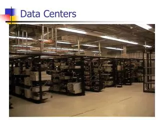
Data Centers Trends
DESCRIPTION
®. Data Centers Trends. Critical Vectors. Operation closer to the “ edge” to realize savings Real time knowledge Autonomic response Fabric architectures FCoE (SAN/FC performance expectations) Two tier architectures –virtualization driven ToR Fat Trees Private “cloud”
Download

1 / 0
Download Presentation

Télécharger la présentation
Data Centers Trends
An Image/Link below is provided (as is) to download presentation
Download Policy: Content on the Website is provided to you AS IS for your information and personal use and may not be sold / licensed / shared on other websites without getting consent from its author.
Content is provided to you AS IS for your information and personal use only.
Download presentation by click this link.
While downloading, if for some reason you are not able to download a presentation, the publisher may have deleted the file from their server.
During download, if you can't get a presentation, the file might be deleted by the publisher.
E N D
Presentation Transcript
- ®
- Data CentersTrends
- Critical Vectors Operation closer to the “edge” to realize savings Real time knowledge Autonomic response Fabric architectures FCoE (SAN/FC performance expectations) Two tier architectures –virtualization driven ToR Fat Trees Private “cloud” Power/cooling – more than just reporting Infrastructure as a “CMDB element”
- Data Center Evolution/Trends Application Architecture Evolution Centralized Decentralized Virtualized Client-Server and Distributed Computing Service Oriented Mainframe Consolidate IT Relevance and Control Virtualize Automate
- Data Center/Converged Ethernet facilitates I/O Consolidation for increased Efficiency, Simpler Operations Unified Fabric Storage Network Storage Network Mgmt Network Backup Network Backup Network Mgmt Network Back-End Network Back-End Network Front-End Network Front-End Network Unified Fabric and I/O
- I/O Consolidation: Benefits to Users FC Traffic FC Traffic SAN A SAN B Enet Traffic Enet Traffic FCoE SAN FCoE FCoE FCoE FCoE Fewer NICs and Cables Unified Management Model Less Power and Cooling
- 40 & 100 Gig Standard EthernetUpdate
- 802.3ba 40/100Gigabit Ethernet Overview IEEE 802.3ba was ratified June 2010 8 PMDs are included Multimode requires MPO/ribbon to port Short reach copper cable assembly is included Traditional Structured Twisted pair cabling is not included
- 802.3ba Summary of Options
- 40GBE over Copper Included in 802.3ba standard 8-pair Twin-ax Cable Assembly QSFP Modular Interface 7m (23ft) reach Similar application space as 10GSFP+Cu for ToR/POD layouts Larger OD vs. SFP+ Planned release Q4 10 (prototypes available Q3) QSFP OD: 0.36in/9.2mm (24AWG) SFP+ OD: 0.22in/5.6mm (24AWG) QSFP Cable Assembly
- 100GBE over Copper 20-pair twin-ax cable assembly Cable is large approx 0.5in OD CXP Modular Interface (similar to 12X IB) Under research to understand market need May transition to 25G x 4 in QSFP form factor in future 20-pair twinax, approx 0.5 in. OD CXP Form Factor
- 40GBE over Multimode Fiber QSFP SR Transceiver OM3: 100m, OM4: 150m QSFP transceiver with 12 fiber MTP/MPO connector Uses outside 4 fibers on each side for Tx and Rx Existing Panduit OM3 and OM4 MTP cables are good for 40GBE Since 10G TCVRs use duplex fiber more ribbon fiber is required in the cable plant for 1 to 1 migration (6x) MTP Cable Assembly
- 100GBE over Multimode Fiber 100G over MMF requires CFP module today Most CFP will use 24 fiber MTP interface Will need to breakout 24 fiber to 2 x 12 fiber patch to connect to fiber plant 10GBASE-SR10 CFP with 24 fiber MTP Interface Fiber plant connections
- Innovative technology leadershipEnd-to-end physical infrastructure solutions Connectivity and Cabling Cabinets and Racks Cable Management Physical Infrastructure Management Zone Cabling Routing Grounding Labeling and Identification Security and Identification Accessories Design Tools and Services
- Innovative technology leadership High Speed Data Transport Comprehensive Copper and Fiber Cabling Systems High Performance Technology 10 Gigabyte Ethernet Fiber Channel InfiniBand Pre-Terminated Options 75% Faster Deployments Integrated Copper/Fiber Optic Combinations High-Density Applications
- TX6A 10Gig Cabling System With MaTriX TechnologyComplete End-to-End Cabling Solution Patch Cords Horizontal Cable Jack Modules Patch Panels Advanced electrical compensation technology Innovative foil technology to suppress alien crosstalk 100% performance tested Channel & component compliant Innovative matrix tape technology to suppress alien crosstalk 0.290 in. O.D. diameter Stranded, flexible cable design centre de-embedded plug with internal pair manager 100% performance tested High-density applications -- 48 ports 1RU Angled or straight 100% performance tested Channel & component compliant Innovative matrix tape technology to suppress alien crosstalk 0.30 in. O.D. diameter Round cable design Extended temperature range (75oC) Channel & component compliant
- TX6A 10Gig Copper Cabling System Evolution of MaTriX Technology Changes to MaTriX Tape MaTriX Tape’s key feature: Discontinuous Metallic Elements help suppress Alien Crosstalk New Manufacturing Technology: LASERS! Advanced Manufacturing process uses lasers to create new MaTriX tape Larger Discontinuous Metallic Elements = Improved Alien Crosstalk Thinner tape = Smaller Cables
- 10GBase-T EcoSystem Launch Matrix Tape suppresses alien xtalk Barrier layer improves attenuation Outer Jacket Cross-Web Twisted Wire Pairs Cost Effective, High Performance, Highly Available Next-Generation Server Connectivity Category 6 UTP/STP Type Cabling with distances of up to 55m Category 6A UTP/STP and Category 7 STP Type Cabling with distances of up to 100m
- Cisco Catalyst 6500 16-Port 10GBase-T Line Card Deployment Areas Data Center Access Distribution Key Features 16 port, 4:1 oversubscribed 10Gbase-T line card 802.3an compliant Up to 100 meters reach Same fit form and function as other line cards for the Catalyst 6500 Interoperability – works with all 802.3an standard NIC and MAC
- Cisco Catalyst 4900M 8-Port 10GBase-T Line Card Deployment Areas Data Center Access Data Center Distribution Key Features 8 port, 2:1 oversubscribed 10GBase-T line card 1/10GE auto-negotiating 802.3an compliant Up to 100 meters reach Same fit form and function as other half cards for the Catalyst 4900M Interoperability – works with all 802.3an standard NIC and MAC
- Intel 10 Gigabit AT2 Server Adapter Intel’s second-generation 10GBASE-T server adapter Based on the Intel® 82598 10 Gigabit Ethernet Controller Designed for multicore processors, optimized for virtualization, and supports iSCSI Delivers cost-effective, low power single port 10GbE performance
- High frequency, up to 10GHz/pair Parallel shielded pair (twinax) Factory soldered terminations Point to point interconnects Applications 10GBE-CX4 InfiniBand 10G SFP+ 40GBE High Speed Twinax Cable Assemblies
- SFF-8431 compliant Passive - no additional power per port Low latency Robust easy to use latching 100% tested for performance and quality assurance Superior performance margin assures data integrity 1 – 7 m(33ft) in 0.5m increments Max. operating length depends on host ports and application; 7m for 10GBE, 5m for FCoE 2 colors for A & B networks (Blue/White) Longer cables in development Panduit 10Gig™ SFP+ Cable Assembly Benefits
- 10GigTM Server Connection Options NEW! SFP+ copper solution Low cost Low power and low latency Up to 7m (23ft) for in-rack and in-row cabling
- Server Switch 10 m PHY PHY CX1-SFP+ CX1-SFP+ 0.0W ($130) 0.75W ($35) 0.75W ($35) 1 m 8 m 1 m PHY PHY RJ45 RJ45 RJ45 RJ45 0.0W ($6) 0.0W ($27) 0.0W ($6) 4W ($60) 4W ($60) 10 m PHY PHY OM3 SFP+ OM3 SFP+ 0.0W ($50) 0.5W ($175) 0.5W ($175) 0.75W ($35) 0.75W ($35) CapX Assumptions: - PHY cost to Price =2x - PHY/Trans cost red. = 10%/yr - Transceiver cost to Price = 5x - Cabling is price - Cabling cost red. = 2.5%/yr OpX Assumptions: - 12 cents per kWh - $ per year
- Parameters limiting channel performance: Fibre Bandwidth / Dispersion (chromatic and intermodal) Connector Insertion Loss Fibre Attenuation Optical Impairments / Power Penalties (RIN, MPN, MN, RN & PN) Transceiver output power levels, sensitivity and ISI Conditions influencing Link Loss, Power Penalties, Fibre BW Mode Power Distribution (affects IL and fibre bandwidth) Spatial Mode Filtering (affects IL and MN) Defects in fibre core – location & type (affects fibre bandwidth) New Effect Discovered by Fibre Research (previously unknown) Research Tools Used To Study Link Performance Bit Error Rate (BER) Analysis (measures channel performance) Differential Mode Delay (DMD) Measurements (fibre bandwidth) Near-field Imaging (optical power distribution) Optical Spectrum Analysis Fiber Cabling SystemsResearch in Optical Link Performance
- Quantification /Verification of contributing factors to 10G-Base-SR channel performance: Explore parameters effecting fiber bandwidth Inter modal dispersion Chromatic dispersion attenuation System Performance Parameters BER versus EMBc DMD versus BER Channel Certification Panduit specification Field testing 4020 MHzhkm 4020 MHzhkm 27
- Fiber Cabling SystemsBERT - Fiber Manufacturer Approval and Compliance 1390 MHzhkm 1629 MHzhkm 6494 MHzhkm
- Fiber Cabling SystemsHigh Resolution/World Class DMD Test Capability Laser spectral and temporal widths optimized for 300m length – 10GBASE-SR reach requirement Highest spatial resolution in the world (0.1 micron)
- Fiber Cabling SystemsFiber DMD Testing Panduit DMD EMBc = 6,343 MHzhkm Commercial DMD Test Set EMBc = 10,324 MHzhkm
- Fiber Cabling SystemsBandwidth Competitive Analysis Panduit OM3 Competitor’s OM3 and OM4 Distributors: Anixter Graybar Prysmian FIS 11.8% Failed
- PIM / PVIQ Solution
- Software & Appliance Market Evolution – 2010 to 2015 Systems Management Software Single converged physical infrastructure management software by 2012 / 2013 Source: Gartner ITOM Report 3/09 Hi PI Policies Open APIs for systems software integration What Leading Industry Analysts are Saying… “Infrastructure and operations (I&O) leaders must now go beyond performance management of IT equipment and begin to manage the entire data center infrastructure. Tools for data center infrastructure management (DCIM) will provide detailed monitoring and measurement of data center performance, utilization and energy consumption, supporting more-efficient, cost-effective and greener environments.” –David J. Cappuccio, Gartner March 2010 What Leading Industry Analysts are Saying… “The long-term value of DCIM is tied to a product’s ability to integrate with other system management tools or orchestration tools that optimize data center workloads.” –Galen Schreck of Forrester Research December 2009 Integrated Functionality Data Center Infrastructure Management Relative Customer Business Value Physical Resource Infrastructure Management Provisioning, configuration, change management Security& policy management Focus on agility & total economic investment Intelligent Physical Layer Management Lo Hi Breadth of Functionality/Scope
- Panduit Physical Infrastructure Software & Appliances Strategy Software Functionality Network connectivity (Datacentre & enterprise) Provisioning, change, configuration, problem, events, security Real-time information& related automation Energy monitoring & management, space, speed management Efficiency & effectiveness of operations Reference Architectures & Design Tools Energy aware, high performance Open APIs and Integration with Systems Software Leaders (IBM, HP, Microsoft, EMC, and others)
- Integration of Panduit Solution with System Software Chargeback and Accounting Asset Lifecycle Management Data Center Automation Business Impact / Service Level Management Monitoring and Event Managment Connected Smart Buildings Unified Physical Infrastructure (UPI) Smart Data Centers
- Cabinet Top Temps vs. Used Power ASHRAE recommendations.(18-27 C or 64.4 deg F through 80.6 deg F)
- Cabinet Elevation View
- % diff between Top & Bottom Cabinet Temp Area of interest – room for improvement
- Using PUE to Help Measure Efficiency Total Facility Power • The PUE (Power Usage Effectiveness) is a simple ratio for assisting in measuring datacenter efficiency. It compares total electrical power at the intake to power delivered to IT equipment. • PUE is a snapshot in time and is entirely influenced by a site’s M&E configuration, environmental conditions and Tier rating, PUE cannot be readily used to compare one site with another but is used to track the efficacy IT Equipment Power
- Pushing the envelope Exploring the ASHREA Window 2004 specifications bound between 20-25 Degrees C ASHREA worked closely with IT manufacturers to expand this window/region. This included decreasing the dry bulb lower limit to 18 degree C and increasing the upper limit to 27 degrees C. DRY BULB LOWER LIMITThere is no concern from an IT standpoint in lowering the operating condition from 20 to 18°C (64.4°F). The goal here was to extend the control range of economized systems by not requiring a mixing of hot return air to maintain the previous limit. DRY BULB UPPER LIMITThe justification for increasing the dry bulb limit was to increase hours of economizer use per year. Concerns about increasing inlet temperature causing lower reliability are not well founded. IT Equipment manufacturers test, confirm, and state, through ASHRAE, that operation within the recommended limits will not affect equipment reliability
- Innovative technology leadershipCabinets and racks Manage, Protect, and Showcase Installations: Accessible Pathways Improve Speed of Installations/Maintenance Thermal Management Cabinet System Ducting Ventilation Paths Perforated Doors Raised Floor Grommet Reduces operating costs up to 14%
- Integrated solutions
- Innovative technology leadership Cable management Manage, Protect, and Showcase Cable Routing High Density Works with flat and angled patch panels to maximize density and utilization of cabinet and rack space Reduced Real Estate Can Minimize Floor Space and Costs by 23% Integral Bend Radius Helps Maintain Network Reliability
- Innovative technology leadership Zone cabling Shorten Horizontal Cables Using Main Distribution Points Zone Distribution Areas Reduces Cable Congestion Rapid Deployment of Connections Server Cabinet Deployments Creates Staging Areas Plug and Play Deployments Storage Area Isolation Accessibility to Connections Security from Intrusion/Damage
- Innovative technology leadership Routing Systems Manage High Performance Communication, Computing and Power Cables Overhead Pathways High Density Applications Quick Assembly Features Up to three times faster than traditional bolt-together systems Under floor Pathways Protection of High Cable Capacities Grounding Features
- Innovative technology leadership Grounding Systems Protect Network Equipment and Personnel Provides Protection of Personnel and Equipment Critical Factor for Reliable & Efficient Network Performance NEBS Level 3 Compliant Components May Prevent up to $500M/Year of Property/Equipment Damage Due to Lightning
- Innovative technology leadership Labeling and identification Properly Identify Networks to Simplify MACs and Trouble-Shooting Hand-Held Thermal Transfer Printers Software and Labels for Desktop Printers Faceplates Marker Ties Patch Panels Surface Mount Boxes
- Patch Cord Color Band Fits any PANDUIT patch cord Easily attached and removed 8 colors for multiple layers Innovative technology leadership Security & Identification Accessories Lock-In / Block-Out Device Fits any RJ45 jack Requires special removal tool
- Thank You


More Related
Audio
Live Player