Detailed Specifications for QuickEdge PVC Cap and Cable Tray Layout Adjustments
This document outlines the specifications for the QuickEdge PVC Cap (6" and 10.5/8") in conjunction with existing cable pier locations. It includes detailed dimensions, hole placements, and a comprehensive overview of the proposed changes to the cable tray system. Specific attention is given to the adjustments needed for clearance, pier relocation, and the new layout of cable trays. Additionally, it addresses questions regarding the layout of equipment and door placements in the Y-End Electronics Room. Clarifications on missing components and relocation suggestions are provided.

Detailed Specifications for QuickEdge PVC Cap and Cable Tray Layout Adjustments
E N D
Presentation Transcript
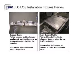
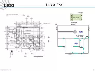
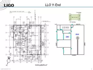
LLO Y-End ¾” QuickEdge PVC – 6” Cap PVC – 6” Cap PVC – 6” x 10 5/8” QuickEdge 6+” hole centered 24” up, 39” over VEAY CERY
VEAY LLO Existing Cable Piers Locations 92.5 95.0 144.0 12.0 24.0 Waterfall 115.0 12.0 Corner Station ® Waterfall 426.0 84.0 43.0 95.0 20.0 44.0 Hole 47.0 184.0 192.0 149.0 145.5 119.0 = 10.0 x 10.0 = 4.0 d 46.5 48.0 17.5 Reference (0) ® 408.0 Cargo Door
VEAY LLO Existing Cable Piers Locations 95.0 12.0 24.0 115.0 Corner Station ® VE Pump 26 x 56.5 Waterfall 426.0 ISC 91.0 Hole 144.0 119.0 = 10.0 x 10.0 VAC = 4.0 d 48.0 Reference (0) ® 408.0 Cargo Door SUS ISCB5R 72 x 48
VEAY Overlay Questions and comments: 1) Where does 11U Short Rack (D1001423-v11) go? (Ignore) 2) Where does L1-AOS-YR1 (if it needs to exist) go? (Does not exist) 3) What does pentagon-2 mean regarding tray removal? Is there tray across the beam tube from L1-SUS-YR1? (Ignore) 4) Is the called-out 10’ height important for some reason? LLO height is 8’. (OK) 5) What are the double doors in the note all about? (Ignore) 6) A door is missing from the garb room to the VEA. (Ignore) 7) The doors are missing from the mechanical room. (Ignore) 8) L1-VAC-YR1 is missing. (Shown) 9) All cabling that currently uses under-beam tray and the waterfall is missing. (Kurt) 10) The Photon Calibrator is missing. (Mounted to tube – part of OPLEV) 11) VE Pumps are not shown. (Shown) 12) Size of ISCB5R is not specified. (72 x 48) Things that can be done: (Note: Green trace is new tray.) 1) Remove old cable tray and pier that interferes with dome parking. 2) Relocate existing piers to support cable tray to L1-SUS-YR1. 3) Locate L1-ISC-YR1 farther away from existing pier for clearance. 4) Suggest joining basket around BSC to existing cable tray at waterfall. 5) Add cable tray to reach L1-SUS-YR1. 1 4 3 2 5 Existing layout New layout
CDS Electronics Room Y-End (CERY) Rack Layout << Y-End Racks It is 65’ from the L1-FAC-YC1 Rack to the knee of the waterfall in the VEAY. The height of the cable trays is 8’. (L1-FAC-YC1) (L1-SUS-YC2) (L1-DAQ-YC1) (L1-TCS-YC1) (L1-SUS-YC1) (L1-SEI-YC1) DC Power Signals and Fiber (L1-VDC-YC1) (L1-VDC-YC2) AC Power CERY